Explosion prevention type electric hot-water bottle

An electric hot water bottle and explosion-proof technology, which is applied to electric heating devices, ohmic resistance heating, electrical components, etc., can solve the problems of complex structure, failure of protection switch, burst of hot water bottle, etc., to achieve a simple overall structure, ensure normal operation, and improve safety. Effect

Inactive Publication Date: 2009-03-04
高国兴
View PDF3 Cites 3 Cited by
  • Summary
  • Abstract
  • Description
  • Claims
  • Application Information

AI Technical Summary

Problems solved by technology

The main disadvantage of this kind of electric hot water bag is that the gas generated when it is heated by electricity will not be discharged automatically, and the cover plug on the water injection port on the surface of the hot water bag must be manually opened to release the gas, which is inconvenient and unsafe. The gas inside increases with repeated heating, and the pressure is too high to cause the hot water bag to burst, causing an accident
[0003] As an improvement of the above-mentioned hot water bag, Chinese utility model patent: ZL02223120.X discloses an "explosion-proof electric hot water bag" (its publication number: CN2564135Y), which is equipped with an automatic exhaust device on its structure, but its structure is relatively complicated. It is not easy to manufacture, and the reliability of work is not ideal enough; another example is the Chinese utility model patent: ZL200520102925.3, which discloses a kind of "electric hot water bag" (its publication number: CN2807680Y). The connection length of the socket and the dislocation of the height of the two electrode heating rods on the fixing seat improve the working sensitivity. Although the structure is simple, the water injection volume is not easy to control, and the reliability is not ideal.
[0004] For this reason, the applicant applied for a Chinese invention patent application "An Explosion-proof Electric Hot Wa...

Method used


Image

  • Explosion prevention type electric hot-water bottle
  • Explosion prevention type electric hot-water bottle
  • Explosion prevention type electric hot-water bottle

Examples


Embodiment

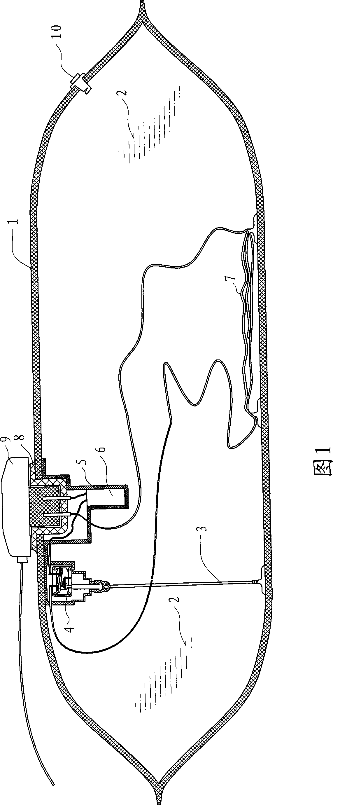
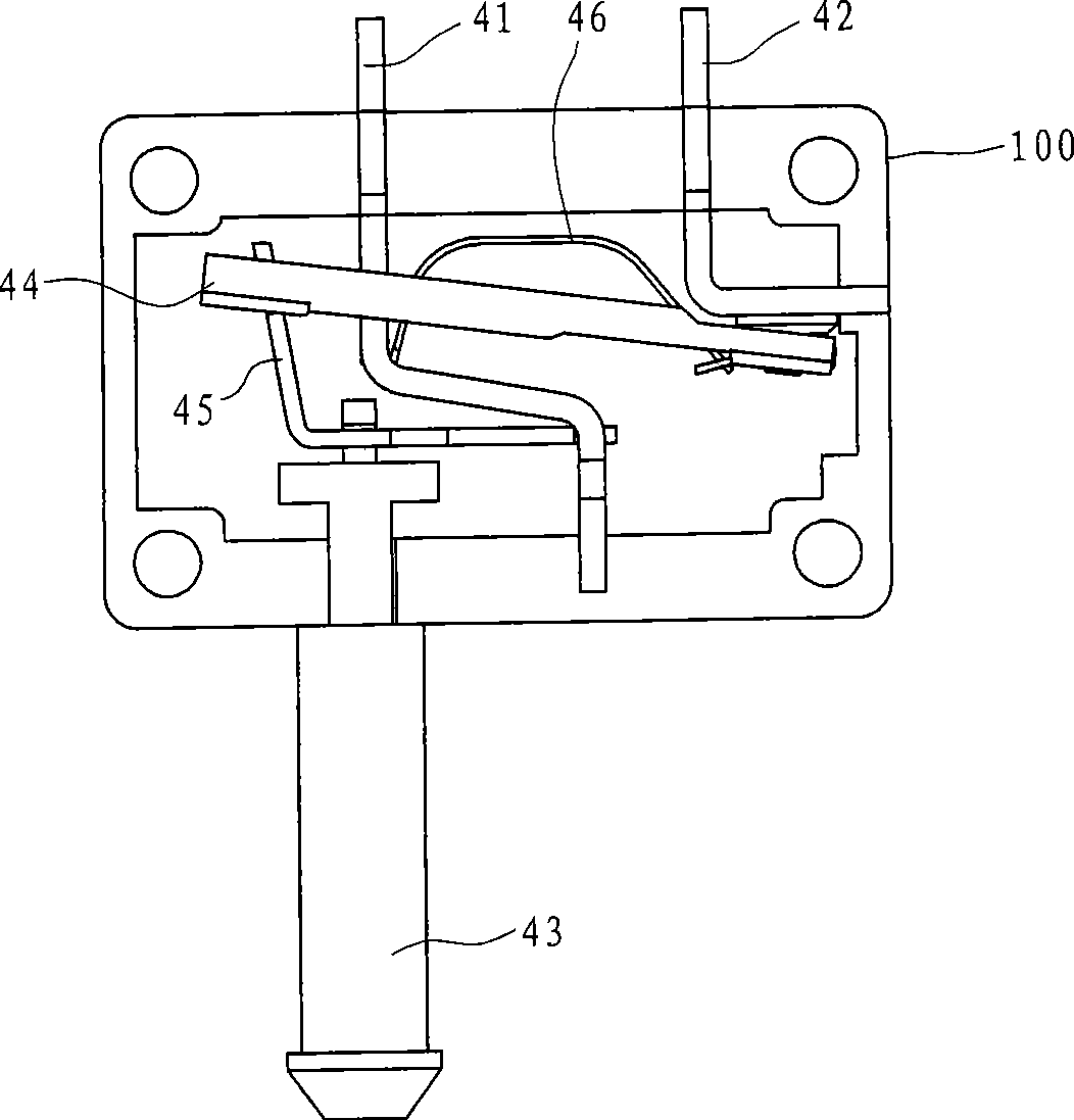
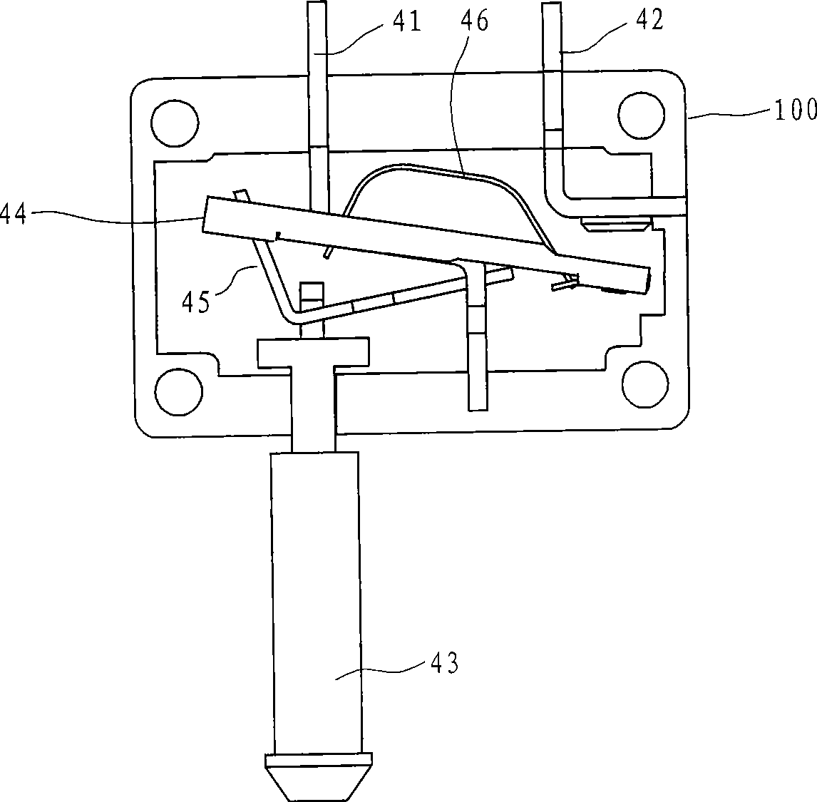
[0029] Embodiment: As shown in FIG. 1, the explosion-proof electric hot water bag in this embodiment includes a closed soft bag body 1, a waterproof casing 5, a temperature controller 6, a liquid 2 serving as a heat storage medium in the bag body 1, and The heating element 7, the bag body 1 is provided with an electric socket 8, a protection switch 4 and a pull cord 3, the protection switch 4 is connected in series on the power circuit of the heating element 7, and the bag body 1 is provided with an electric socket 8 and an electric socket 8 The connected thermostat 6 and the electric socket 8 can be connected with an electric plug 9, and the bag body 1 is also equipped with an exhaust liquid injection hole 10, and the thermostat 6, the protection switch 4 and the electric socket 8 are all located in the waterproof casing 5, The stay cord 3 can drive the pull rod 43 to pull back. The upper end of the stay cord 3 is connected to the outer end of the waterproof casing 5, and the ...


PUM


Abstract

An explosion-proof electric hot-water bag comprises a close-type soft bag body, liquid serving as heat accumulation media in the bag body, and a heating element; a protection switch and a stay cord are arranged on the bag body; the protection switch comprises a housing; a movable contact spring, a still contact spring, a reposition element and a movable pull rod are arranged in the housing; and the stay cord can drive the pull rod to make pullback movement. The bag is characterized in that the still contact spring comprises a first still contact spring and a second still contact spring arranged at intervals; the protection switch further comprises a driving medium; and the reposition element is a reed. Compared with the prior art, the bag has the beneficial effects that instant continuity and disconnection can be achieved by adopting the reed matched with the movable contact spring, the still contact spring, the driving medium and the pull rod; rapid contact and tripping off of the movable contact spring and the second still contact spring are guaranteed; the problem of burning off of inner element caused by linearity stress is effectively avoided; and the normal operation of the protection switch is ensured.

Description

technical field [0001] The invention relates to an electric hot water bag, in particular to an explosion-proof electric hot water bag. Background technique [0002] Currently commercially available electric hot water bags, the outer shell is a sealed bag made of PVC nylon silk, the bag is filled with water, and two rod-shaped heating electrodes are placed in the bag. The electrodes are connected to the power socket on the surface of the hot water bag. There is also a temperature-limiting relay in series with the power supply socket. After the power is turned on, the water between the two electrode rods has a certain resistance. The water acts as a load to convert electrical energy into heat energy. The water temperature rises. , the temperature limit relay will automatically cut off the power to complete a working process. The main disadvantage of this kind of electric hot water bag is that the gas generated when it is heated by electricity will not be discharged automatica...

Claims


Application Information

Patent Timeline
IPC IPC(8): A61F7/00H05B3/00
Inventor 高国兴
Owner 高国兴
Why Eureka
Try Eureka