Novel bubbling bed reactor

A fluidized bed reactor and reactor technology, applied in chemical instruments and methods, petroleum industry, chemical/physical processes, etc., can solve the problems of lower product quality, long residence time, and small operating flexibility, so as to prevent condensation and coking reactions , Ensure efficient separation and increase operational flexibility

Active Publication Date: 2009-03-04
CHINA PETROLEUM & CHEM CORP +1
View PDF3 Cites 98 Cited by
  • Summary
  • Abstract
  • Description
  • Claims
  • Application Information

AI Technical Summary

Problems solved by technology

[0003] A typical fluidized bed process is described in US Re 25,770, but this process method has the following disadvantages in practical application: the amount of catalyst storage in the reactor is small, and the space utilization rate of the reactor is low; the maintenance cost of the circulating oil pump is high, and once Malfunction and damage of the circulating oil pump will cause the catalyst to sink and accumulate, resulting in the forced shutdown of the device; the liquid product in the reactor stays for too long under non-catalytic hydrogenation conditions, and it is easy to undergo secondary thermal cracking reaction at high temperature Coking reduces product quality
The three-phase separator introduced in this patent has a small operating flexibility at the outlet of the three-phase separator and the outlet of the reactor. The catalyst separated by the three-phase separator will stick to the outlet of the catalyst, and the phenomenon of cross-gas is likely to occur at the outlet of the catalyst, which affects the The separation effect of the three-phase separator, and the catalyst brought out is easy to block the downstream device, which is not conducive to the long-term operation of the device

Method used


Image

  • Novel bubbling bed reactor
  • Novel bubbling bed reactor
  • Novel bubbling bed reactor

Examples


Embodiment -1

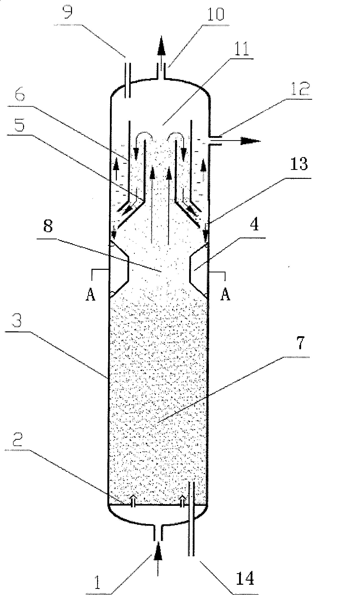
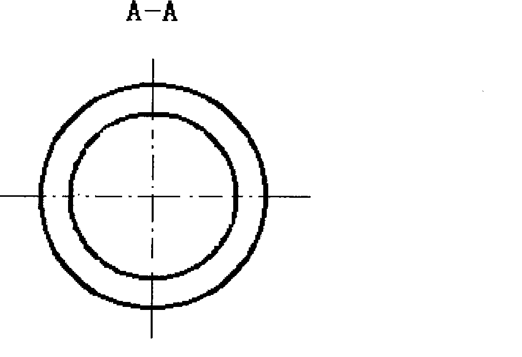
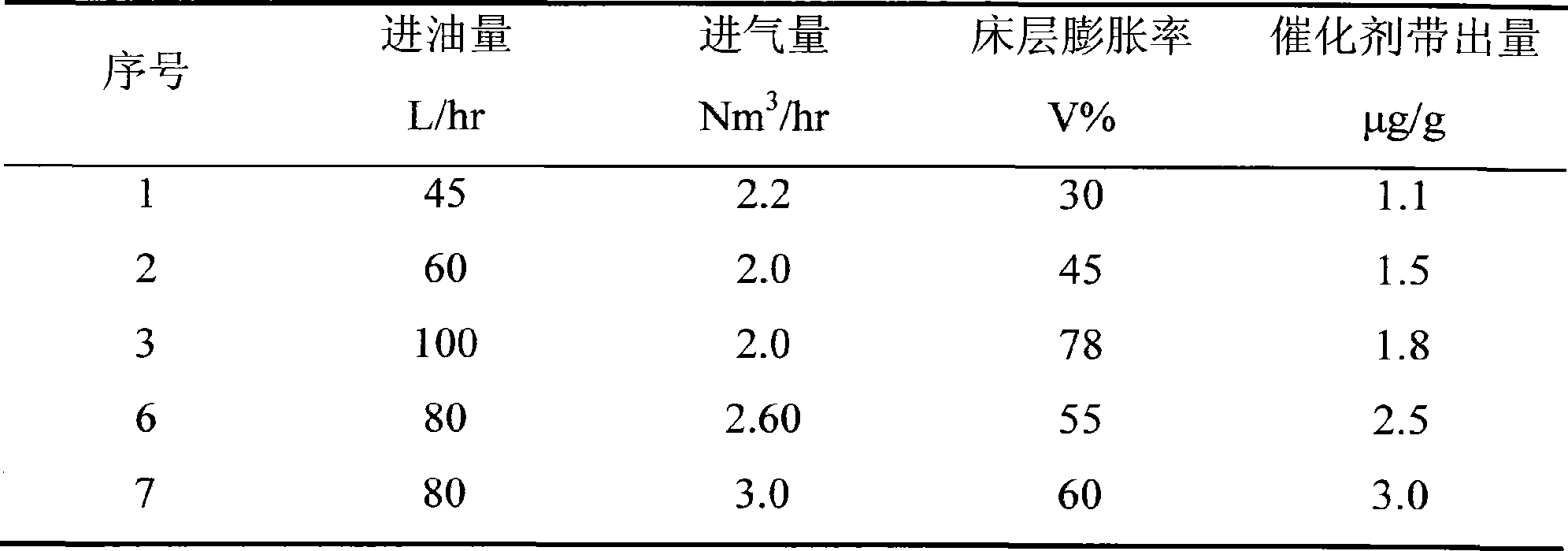
[0030] According to the structure of the ebullating bed hydrogenation reactor of the present invention, a three-phase separator ebullating bed medium-sized reactor cold mold test has been carried out, and the size of the medium-sized cold mold device is: the inner diameter of the reactor shell=160mm, the reactor shell Height = 3000mm, shell effective volume 60L, separator height = 380mm, diameter of the cylindrical part of the central tube of the separator = 92mm, bottom diameter of the tapered opening at the lower part of the inner cylinder = 144mm, height of the lower cone part of the inner cylinder = 41mm, The diameter of the cylindrical part of the outer cylinder = 128mm, the bottom diameter of the opening of the tapered part = 138mm, the height of the tapered part = 64mm, the upper opening of the outer cylinder is higher than the upper opening of the inner cylinder, and the bottom position of the lower tapered opening of the outer cylinder is higher than that of the inner c...

Embodiment -2

[0033] On the basis of the cold model test, a hydrodemetallization test of an island atmospheric residue was carried out on a 60L medium-sized unit. Wherein the size of the reactor is the same as in Example 1, and the test conditions and results are shown in Table 2.


PUM

PropertyMeasurementUnit
friction angleaaaaaaaaaa
diameteraaaaaaaaaa
diameteraaaaaaaaaa

Abstract

The invention discloses a new fluidized bed hydrogenation reactor. The fluidized bed hydrogenation reactor of the invention comprises a cylinder-shaped reactor shell perpendicular to the ground, a three-phase separator arranged at the upper part in the reactor shell and a guiding structure arranged at the middle upper part of the reactor. The guiding structure is an annular convex structure arranged on the inner wall of the reactor and has the lengthwise section of a trapezoid or an arc along the axle of the reactor. The combination of the guiding structure and the three-phase separator increases the operating flexibility of the three-phase separator, and ensures the high-efficiency separation on the three-phase separator, thereby greatly reducing the carrying amount of catalyst. The fluidized bed hydrogenation reactor of the invention can be applied to the chemical reactions between different liquids or gases and solid grains under the condition of contacting, and is characterized by large catalyst inventory, high reactor utility ratio, etc.

Description

technical field [0001] The invention relates to a gas-liquid-solid three-phase ebullating bed reactor, in particular to an improved three-phase ebullating bed hydrogenation reactor for chemical reactions of different kinds of liquid and gas substances in contact with solid particles . Background technique [0002] The ebullated bed reactor is a three-phase fluidized bed of gas, liquid and solid, which can process heavy and low-quality feedstock oil with high metal and high asphaltene content. It has the advantages of small pressure drop, uniform temperature distribution, and constant catalyst activity throughout the operation cycle. , Can add fresh catalyst and take out spent catalyst during operation. [0003] A typical fluidized bed process is described in US Re 25,770, but this process method has the following disadvantages in practical application: the amount of catalyst storage in the reactor is small, and the space utilization rate of the reactor is low; the maintenan...

Claims


Application Information

Patent Timeline
Patent Type & Authority Applications(China)
IPC IPC(8): B01J8/22C10G45/20
Inventor 贾丽胡长禄蒋立敬杨涛刘建锟葛海龙
Owner CHINA PETROLEUM & CHEM CORP
Why Eureka
Try Eureka