Method for manufacturing floor covering and floor covering manufacturing thereby

A ground covering and balancing layer technology, applied in floor coverings, chemical instruments and methods, floors, etc., can solve problems such as complex operations, achieve cost savings, reduce construction costs and time, and prevent manpower

Inactive Publication Date: 2009-03-04
D&J ART
View PDF1 Cites 16 Cited by
  • Summary
  • Abstract
  • Description
  • Claims
  • Application Information

AI Technical Summary

Problems solved by technology

Therefore, complex operations are required when retouching the bottom surface of the building

Method used


Image

  • Method for manufacturing floor covering and floor covering manufacturing thereby
  • Method for manufacturing floor covering and floor covering manufacturing thereby
  • Method for manufacturing floor covering and floor covering manufacturing thereby

Examples


Embodiment 1

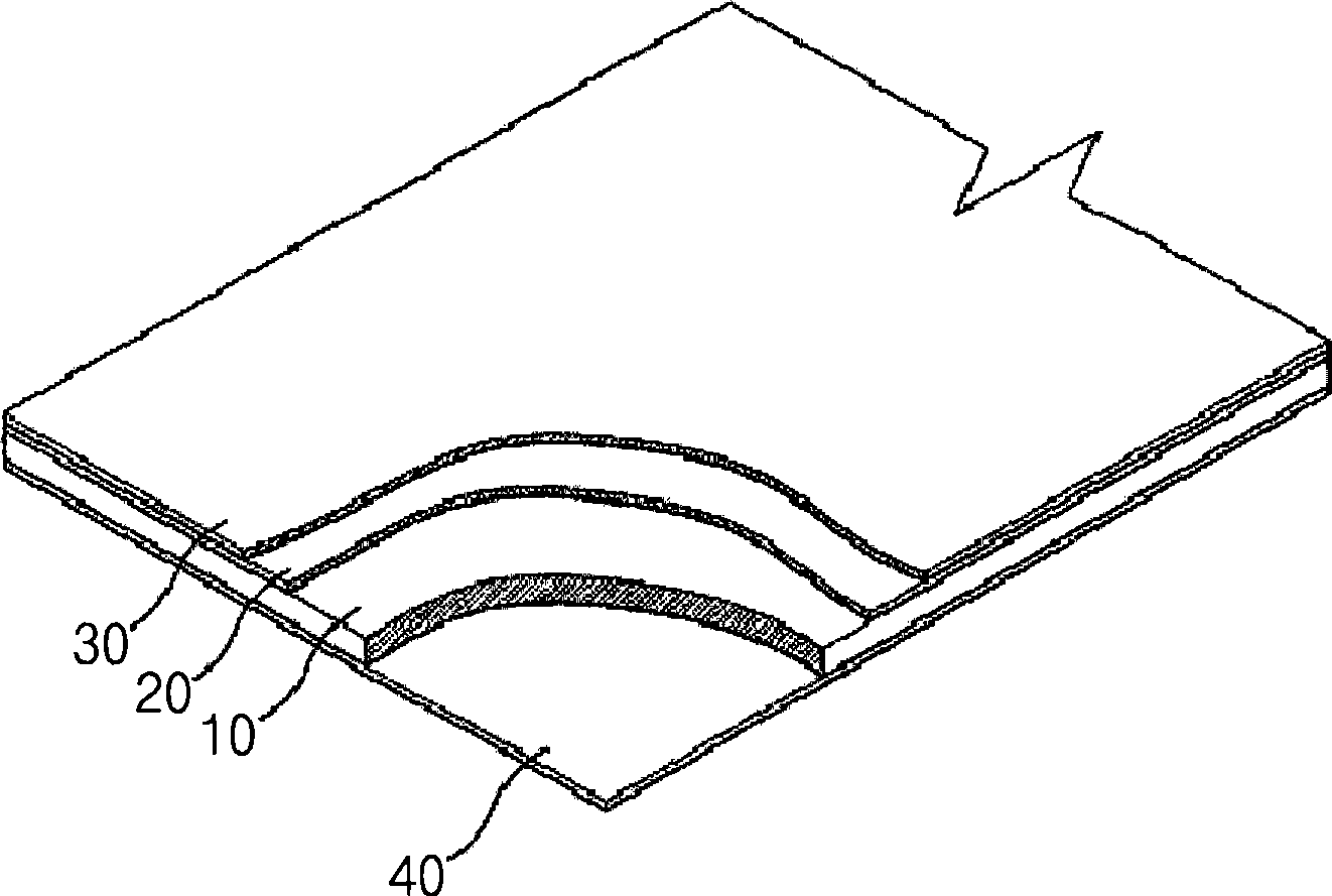
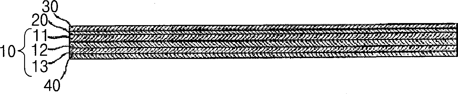
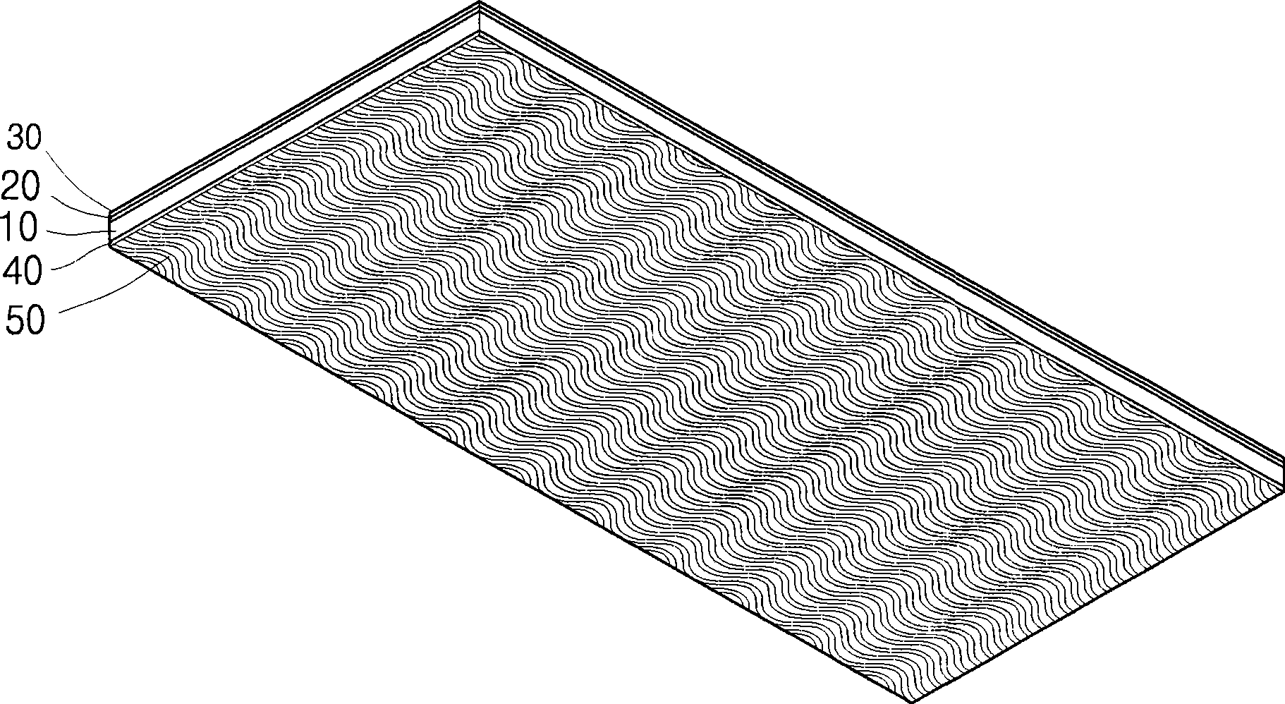
[0052] Manufacture the floor covering in the same manner as Comparative Example 1, and also perform the following additional process of forming a corrugated foam layer under the balance layer to manufacture the floor covering: 100 parts by weight of 1200-1700 The resin composition mixed with vinyl chloride, 120 parts by weight of dioctyl phthalate as a plasticizer and 10 parts by weight of calcium carbonate as a filler is subjected to mechanical foaming.

experiment example 1

[0054] The floor coverings manufactured in Comparative Example 1 and Example 1 were respectively placed on support plates made of cement mortar. , while applying a vertical load of 294 N, the ground covering was pulled at a tensile load rate of 294 N / s and an angle of 18°, and the maximum tensile load (N) was measured by resistance. The results are listed in Table 1.

[0055] Table 1

[0056] Slip performance (N) Comparative example 1 532 Example 1 664

[0057] As can be seen from Table 1, in Example 1 in which the foam layer was formed in the lowermost layer by the manufacturing method of the present invention, it was confirmed that the slipping performance was due to the high friction against cement mortar compared with the slipping type of Comparative Example 1. strength to improve.

experiment example 2

[0059] Sound insulation test

[0060] For the floor coverings manufactured in Comparative Example 1 and Example 1, impact was measured at Korea Noise and Vibration Technology Co., Ltd. according to KS F 2865, KS F 2863-1, KS F 2810-2 and KS F 2863-2 test methods Weighted reduction (ΔLW) of the sound pressure level. The results are listed in Table 2.

[0061] Table 2

[0062] △L W Comparative example 1 6 Example 1 8

[0063] As can be seen from Table 2, in Example 1 in which the foam layer was formed in the lowermost layer by the manufacturing method of the present invention, compared with the slippery type of Comparative Example 1, the weighted reduction of the impact sound pressure level was increased. From this it can be confirmed that the noise is significantly reduced when passing through the floor covering of the example.


PUM

PropertyMeasurementUnit
degree of polymerizationaaaaaaaaaa

Abstract

The invention relates to a method for manufacturing a floor covering including forming a printing layer and a transparent film layer sequentially on a base layer made of polyvinyl chloride (PVC) as a main ingredient, forming a balance layer underneath the base layer, and forming a plurality of foam layers arranged in a row to be equally spaced apart from each other underneath the balance layer is disclosed. The floor covering manufactured by the above has a slip-resistant effect on the floor of a building during the construction. Thus, the construction is carried out without an additional adhesive, and the use amount of the adhesive may be significantly reduced, if being used. Moreover, the floor covering can be replaced immediately without the finishing process, as well as, the recovered floor covering can be recycled since there is no damage thereon. Thus, an eco-friendly construction becomes possible.

Description

technical field [0001] The present invention relates to a method of manufacturing a floor covering with an anti-slip effect and the floor covering manufactured thereby; more particularly, the present invention relates to a method of manufacturing a floor covering and a floor covering manufactured by the method, the The floor covering can reduce the amount of adhesive used in the construction process, and the floor covering can be easily removed and replaced after construction, and can improve sound insulation and cushioning, and increase the friction on the building structure to make it anti-skid. Background technique [0002] In general, floors of building structures require different properties depending on their use. Therefore, in order to meet the needs, choose finishing materials with suitable textures for the structural parts of the ground and ground foundations, and construct using suitable construction methods. [0003] A ground covering such as paper or tiles is fo...

Claims


Application Information

Patent Timeline
Patent Type & Authority Applications(China)
IPC IPC(8): B32B37/02B32B5/18B32B27/28E04F15/00
CPCB32B27/304B32B5/18B32B27/30E04F15/10B32B27/065B32B7/14B32B2307/744B32B5/32E04F2201/095B32B2471/00Y10T428/24802E04F15/02172
Inventor 金德洙高光宪尹昌宝吴哲德
Owner D&J ART
Why Eureka
Try Eureka