
Circuit arrangement and method of driving a high-pressure gas discharge lamp

A high-pressure gas and circuit device technology, applied in the field of headlights, can solve the problems of increased circuit cost, bulky three-way current compensation choke coil, expensive manufacturing, etc., and achieve the effect of reducing electromagnetic interference

Inactive Publication Date: 2009-03-04
LUMILEDS HLDG BV
View PDF4 Cites 1 Cited by
  • Summary
  • Abstract
  • Description
  • Claims
  • Application Information

AI Technical Summary

Problems solved by technology

[0007] Although the previous modification of the current-compensated choke with three windings is very suitable for filtering out disturbing electromagnetic interference, especially in the desired range from 87 to 108 MHz, the latter modification involves passing the first The problem that the three terminals may cause obvious interference
However, the previous improvement has the disadvantage that for this purpose a three-way current compensation choke coil which is expensive to manufacture and relatively bulky should be used, which increases the cost of the overall circuit design

Method used


Image

  • Circuit arrangement and method of driving a high-pressure gas discharge lamp
  • Circuit arrangement and method of driving a high-pressure gas discharge lamp
  • Circuit arrangement and method of driving a high-pressure gas discharge lamp

Examples


Embodiment Construction

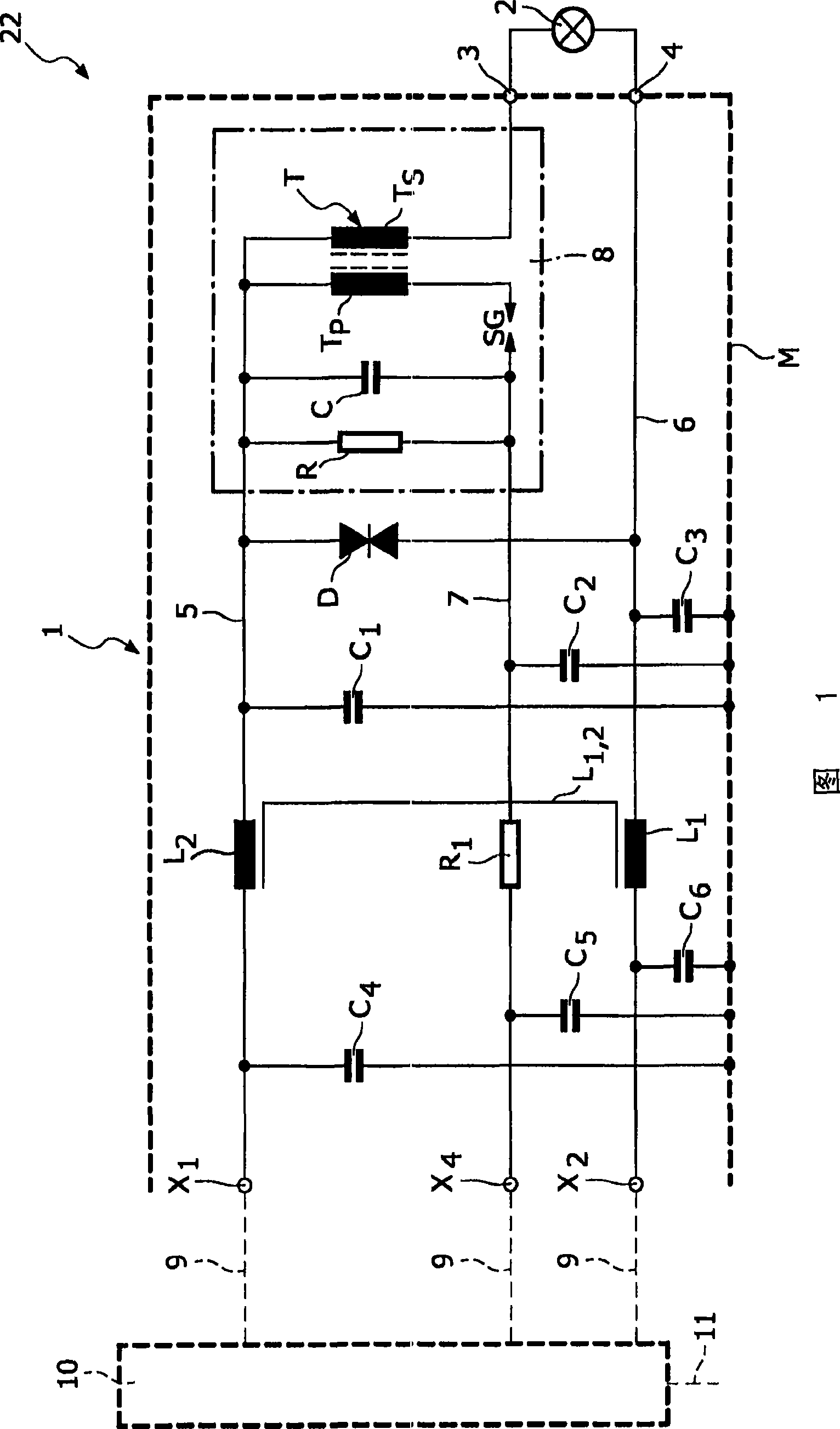
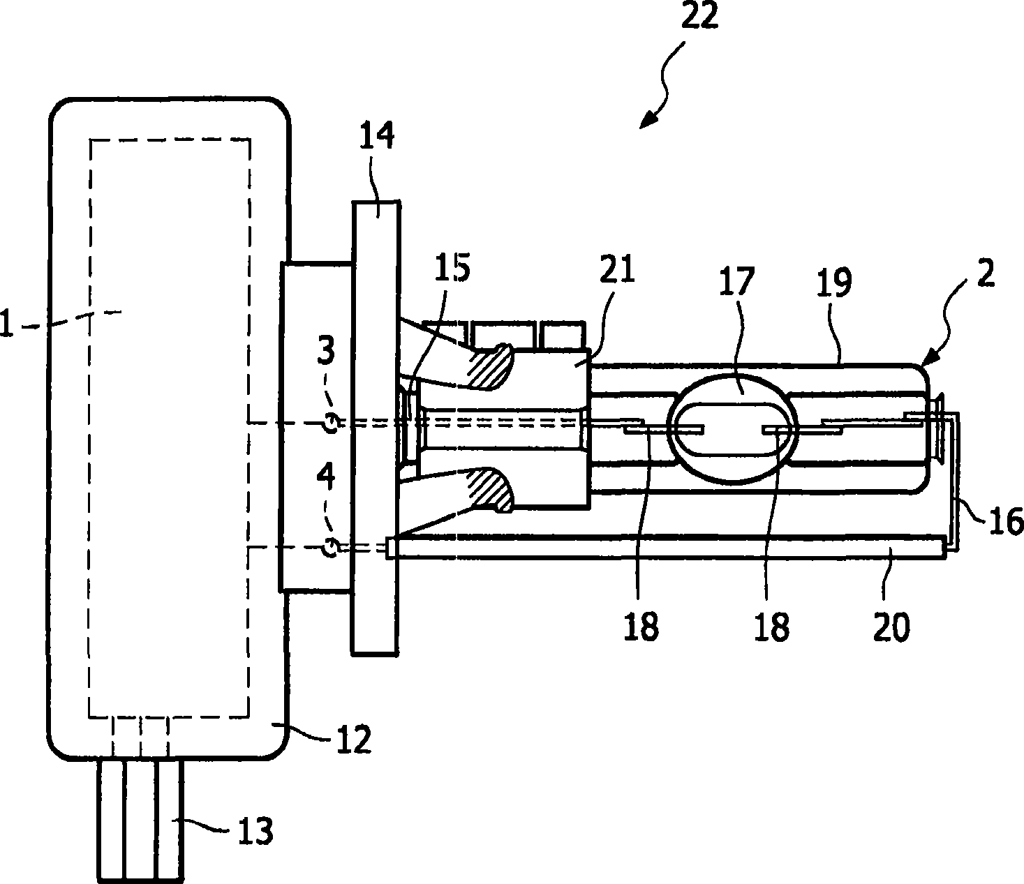
[0032] FIG. 1 shows a first exemplary embodiment of the structure of a circuit arrangement 1 according to the invention for a conventional HID lamp 2 , which can be used, for example, in a motor vehicle headlight. The circuit arrangement 1 has three terminals x on the input side 1 、x 2 and x 4 , the circuit arrangement 1 is connected to the ballast 10 by means of these terminals. This ballast 10 ensures that the necessary voltage potential is applied to the relevant terminal x of the circuit arrangement 1 during ignition of the lamp 2 and in subsequent stable operation. 1 、x 2 and x 4 , and provide the necessary current to the circuit device 1 . The ballast 10 is normally connected to the electrical system of the vehicle by means of a plug-in connector 11 (the ballast 10 with the connector 11 is only schematically shown in FIG. 1 ). On the output side, the circuit arrangement 1 has two terminals 3 , 4 to which the lamp 2 is connected.

[0033] exist figure 2 The mechan...


PUM


Abstract

A circuit arrangement (1, 1', 1'') for driving a high-pressure gas discharge lamp (2) is described, which has a first terminal (x1) for a first voltage potential, a second terminal (x2) for a second voltage potential, and a third terminal (x4) for applying a third voltage potential for igniting the high-pressure gas discharge lamp (2). Furthermore, the circuit arrangement (1, 1', 1'') has a first electrical connection (5) which at its first end provides a first connection terminal (3) for a high-pressure gas discharge lamp (2) and which is coupled by its second end to the first terminal (x1) for the first voltage potential, a second electrical connection (6) which at its first end provides a second connection terminal (4) for a high-pressure gas discharge lamp (2) and which is coupled by its second end to the second terminal (x2) for the second voltage potential, and an ignition device (8) which at its input side is connected at least to the third terminal (x4) and is coupled at its output side to one of the connection terminals (3) for the high-pressure gas discharge lamp (2). Moreover, the circuit arrangement ( 1, 1', 1'') has a first inductor (L1) arranged in the first electrical connection (5), as well as a second inductor (L2) arranged in the second electrical connection (6), which inductors together form a current-compensated choke (L1, 2) through magnetic coupling, and a resistor (R1) of more than 10 O arranged in a third electrical connection (7) between the ignition device (8) and the third terminal (x4).

Description

technical field [0001] The invention relates to a circuit arrangement and a method for operating a high-pressure gas discharge lamp. Furthermore, the invention relates to a lamp unit comprising a high-pressure gas discharge lamp and having such a circuit arrangement as well as a headlight having such a lamp unit. Background technique [0002] Such a high-pressure gas discharge lamp basically comprises a discharge lamp into which two electrodes protrude, generally speaking, the two electrodes are arranged on opposite sides of the discharge lamp, wherein the electrodes are connected to the supply line and reach the discharge lamp arranged in the discharge lamp The sealed part through which the lamp can be connected to the circuit arrangement for supplying power. Discharge lamps are filled with a gas, usually a relatively high pressure noble gas or mixture of rare gases. Typical examples of such high-pressure gas discharge lamps are so-called HID lamps (High Intensity Dischar...

Claims


Application Information

Patent Timeline
Patent Type & Authority Applications(China)
IPC IPC(8): H05B41/292
CPCH05B41/2921
Inventor A·萨维利夫G·托查德斯
Owner LUMILEDS HLDG BV
Learn More