

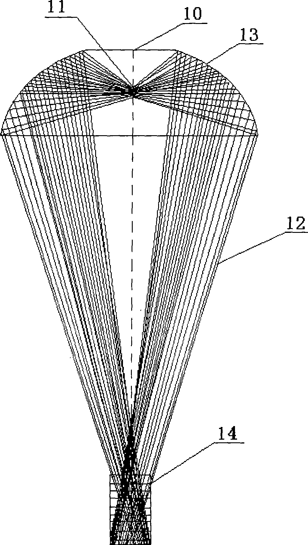
Light path structure for operating astral lamp
A shadowless lamp, light path technology, applied in the direction of light source, point light source, fixed light source, etc., can solve the problems of uneven spot, influence doctor's observation, illumination depth and shadowless degree, etc., to increase the incident angle, eliminate surgical shadows, The effect of easy depth of focus
- Summary
- Abstract
- Description
- Claims
- Application Information
AI Technical Summary
Problems solved by technology
Method used
Image

Examples
Embodiment Construction
[0031] Embodiments of the present invention are described below through specific examples, and those skilled in the art can easily understand other advantages and effects of the present invention from the content disclosed in this specification. The present invention can also be implemented or applied through other different specific examples, and various modifications and changes can be made to the details in this specification based on different viewpoints and applications without departing from the spirit of the present invention.
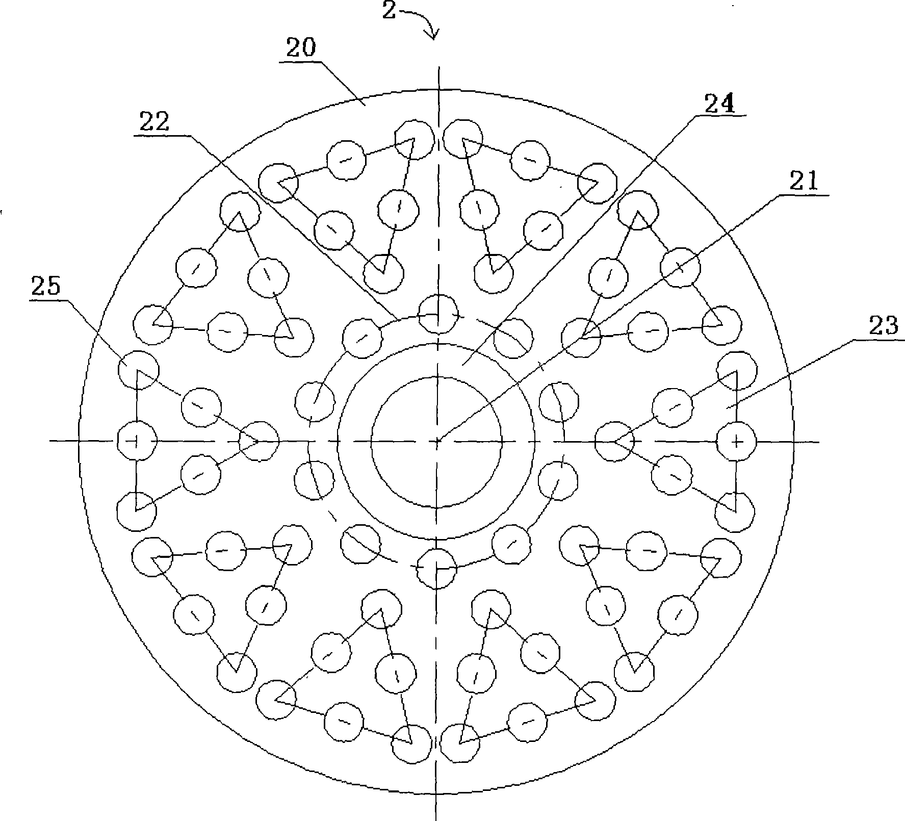
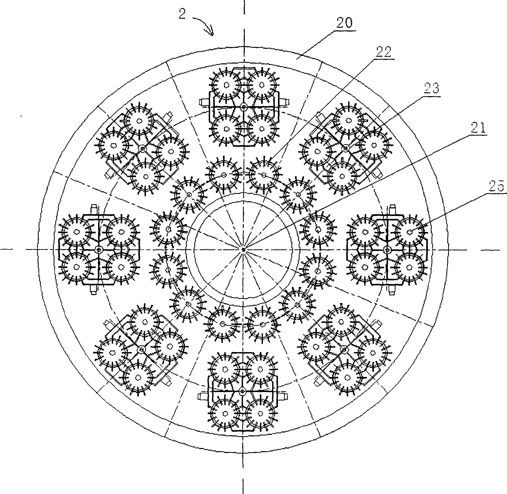
[0032] see Figure 2A and Figure 2B , which is a schematic diagram showing the arrangement of LED light source groups in the light path structure of the surgical shadowless lamp of the present invention. As shown in the figure, the present invention provides an optical path structure of a surgical shadowless lamp. In this embodiment, the surgical shadowless lamp 2 is used in the medical field to provide illumination for doctors when performing...
PUM
 Abstract
Description
Claims
Application Information