Photoelectric encoder and electronic equipment using the same
An encoder and optical technology, applied in the field of optical encoders, can solve problems such as malfunction, gate delay, and output signal duty cycle deviation.
- Summary
- Abstract
- Description
- Claims
- Application Information
AI Technical Summary
Problems solved by technology
Method used
Image
Examples
no. 1 Embodiment approach
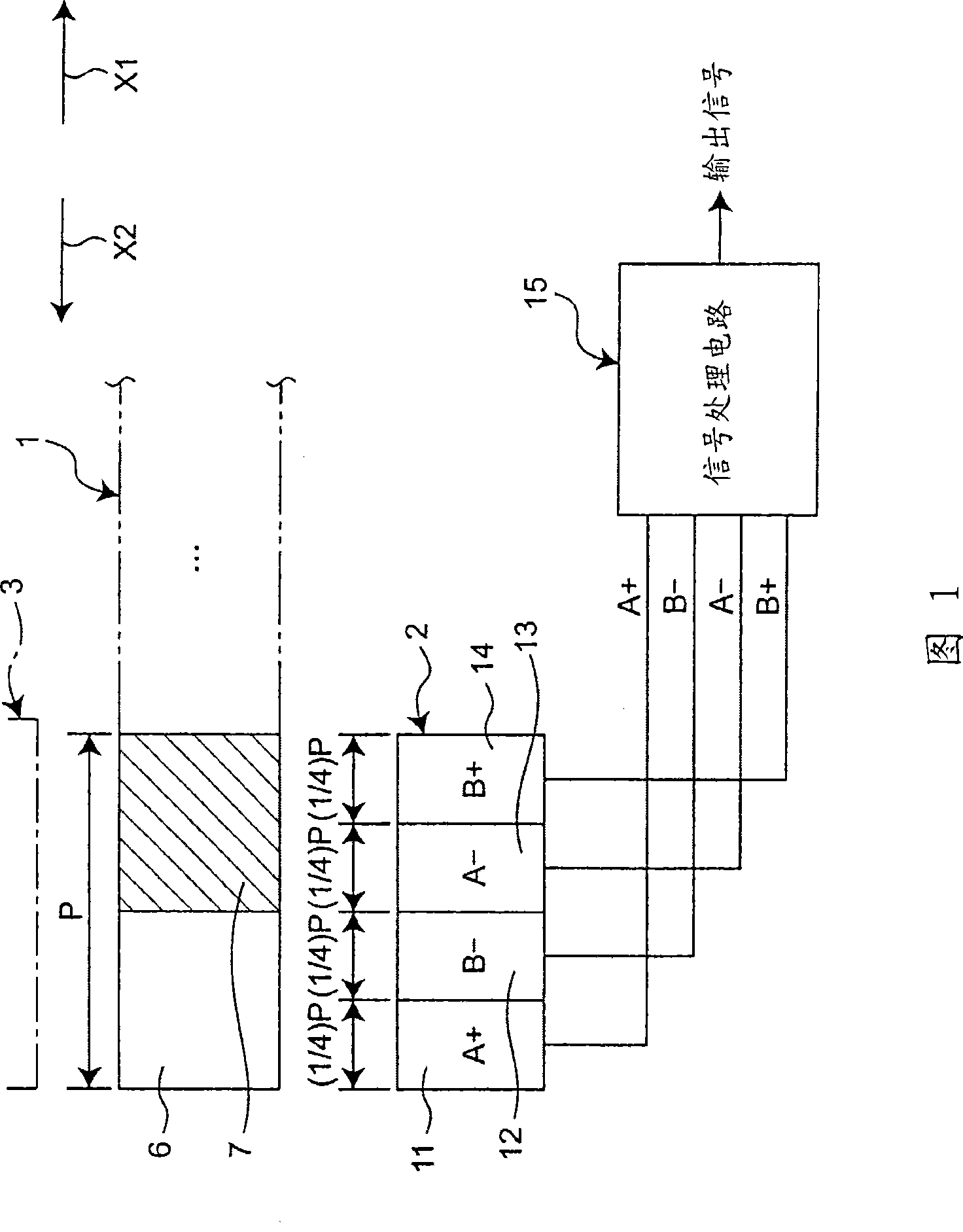
[0058] FIG. 1 shows a schematic configuration of a first embodiment of an optical encoder of the present invention. In this first embodiment, a mobile body 1 , a light receiving unit 2 , and a light emitting unit 3 are included. The light emitting unit 3 is constituted by a light emitting element such as an LED (Light Emitting Diode).
[0059] The light receiving unit 2 has four light receiving elements 11 to 14 . In addition, in order to obtain a higher resolution, it is also possible to use a light receiving unit 2 in which a plurality of light receiving elements such as 8 or 16 are arranged. In addition, the moving body 1 can move in the direction indicated by the arrow X1 or X2, and the light passing portions 6 and the light cutting portions 7 are alternately arranged in the moving direction. Assuming that the arrangement pitch of the light passing portions 6 is P, the dimension (width dimension) in the moving direction of the light passing portions 6 and the light cutti...
no. 2 Embodiment approach
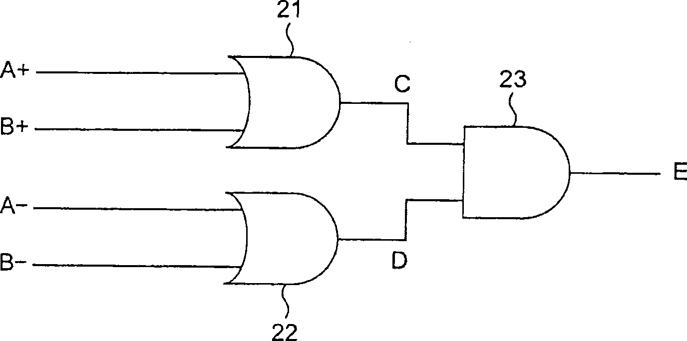
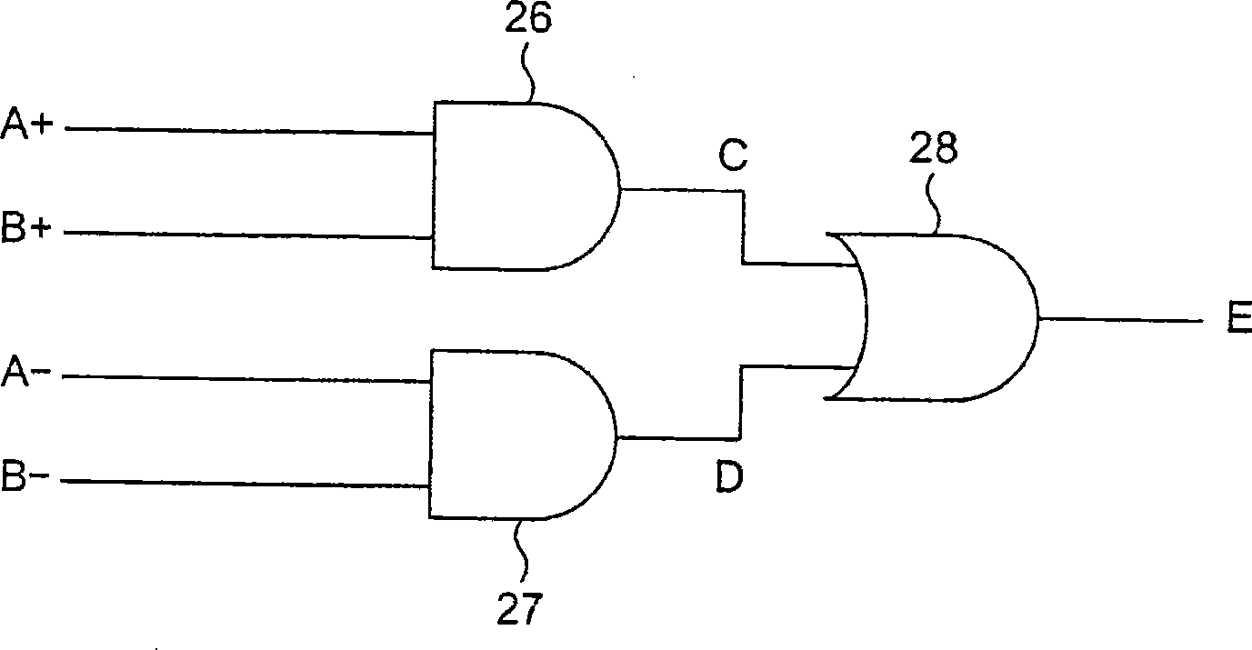
[0068] then, Figure 2B The structure of the signal processing circuit included in the second embodiment of the optical encoder of the present invention is shown. The difference between the second embodiment and the above-mentioned first embodiment is that instead of the above-mentioned first embodiment Figure 2A The signal processing circuit shown, which includes Figure 2B The signal processing circuit shown. Therefore, in the second embodiment, points different from the first embodiment described above will be mainly described.
[0069] Such as Figure 2B As shown, the signal processing circuit included in the second embodiment includes a first AND circuit 26 , a second AND circuit 27 , and an OR circuit 28 . In the first AND circuit 26, the light-reception signal A+ and the light-reception signal B+, which are 90° out of phase with each other, are input. In addition, to the second AND circuit 27, the light-receiving signal A- and the light-receiving signal B-, which a...
no. 3 Embodiment approach
[0096] Next, FIG. 7 shows a configuration of a signal processing circuit included in a third embodiment of the optical encoder of the present invention. The difference between this third embodiment and the above-mentioned first embodiment is that instead of the above-mentioned first embodiment Figure 2A The signal processing circuit shown in FIG. 7 includes the points of the signal processing circuit shown in FIG. Therefore, in this third embodiment, differences from the aforementioned first embodiment will be mainly described.
[0097] As shown in FIG. 7 , the signal processing circuit included in the third embodiment includes first to fourth inverters 81 to 84 , and a fifth inverter to which the outputs of the first and second inverters 81 and 82 are input. 85, and a sixth inverter 86 to which the outputs of the third and fourth inverters 83 and 84 are input. In addition, the signal processing circuit includes: a seventh inverter 87 to which the outputs of the fifth and si...
PUM
 Abstract
Description
Claims
Application Information
 - R&D
- Intellectual Property
- Life Sciences
- Materials
- Tech Scout
- Unparalleled Data Quality
- Higher Quality Content
- 60% Fewer Hallucinations
Browse by: Latest US Patents, China's latest patents, Technical Efficacy Thesaurus, Application Domain, Technology Topic, Popular Technical Reports.
© 2025 PatSnap. All rights reserved.Legal|Privacy policy|Modern Slavery Act Transparency Statement|Sitemap|About US| Contact US: help@patsnap.com


