Flow speed measurement sensor

A flow velocity measurement and sensor technology, applied in fluid velocity measurement, measuring device, velocity/acceleration/impact measurement, etc., can solve the problem of not being able to measure water flow velocity in time, achieve less influence, better measure water flow, and improve linearity Effect

Active Publication Date: 2010-07-14
KUNSHAN SHUANGQIAO SENSOR MEASUREMENT CONTROLLING
View PDF3 Cites 0 Cited by
  • Summary
  • Abstract
  • Description
  • Claims
  • Application Information

AI Technical Summary

Problems solved by technology

However, due to the large inertia of the liquid column in the pycnometer, the speed of the water flow cannot be measured in time during the dynamic measurement.

Method used


Image

  • Flow speed measurement sensor
  • Flow speed measurement sensor
  • Flow speed measurement sensor

Examples


Embodiment Construction

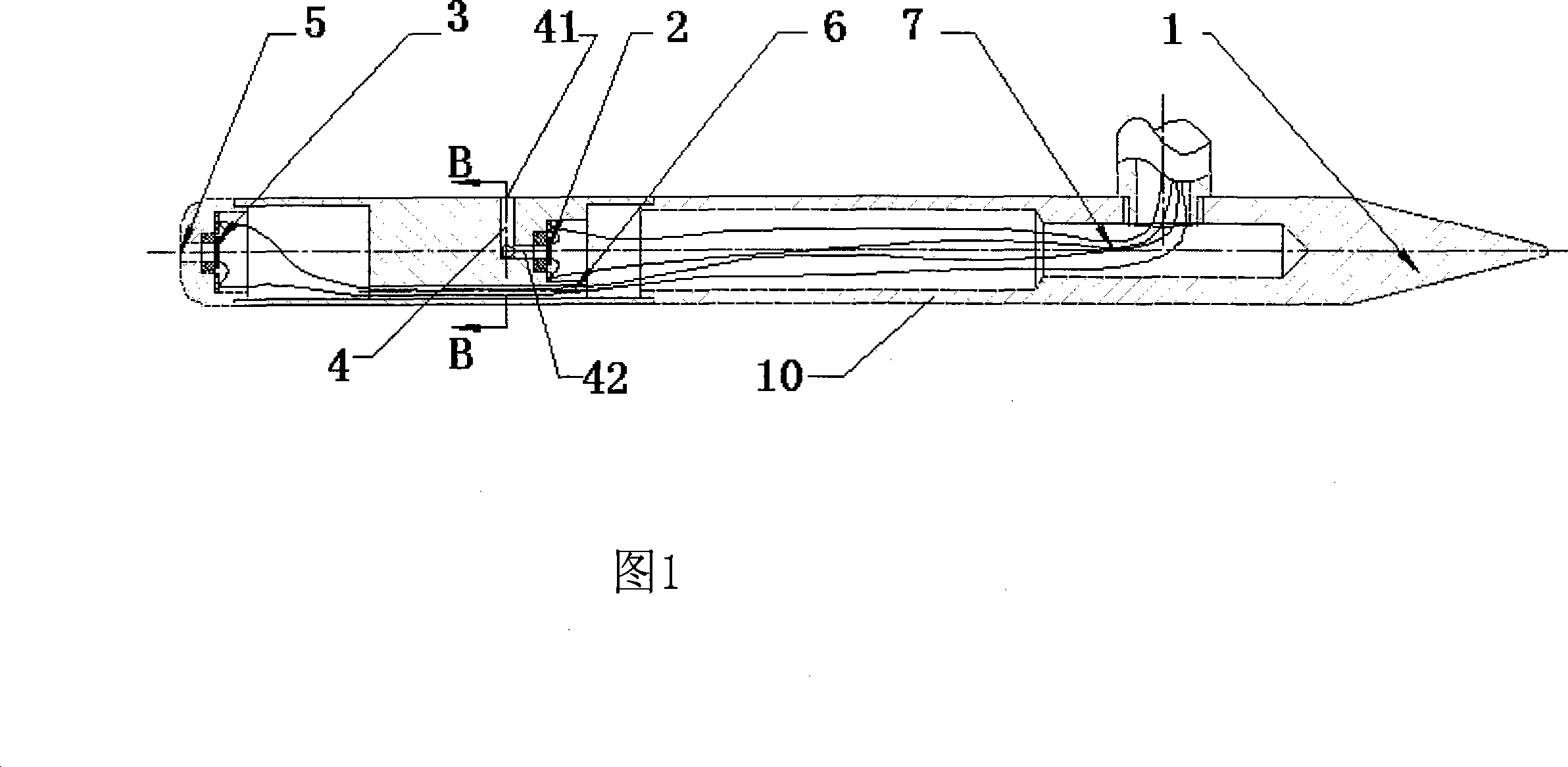
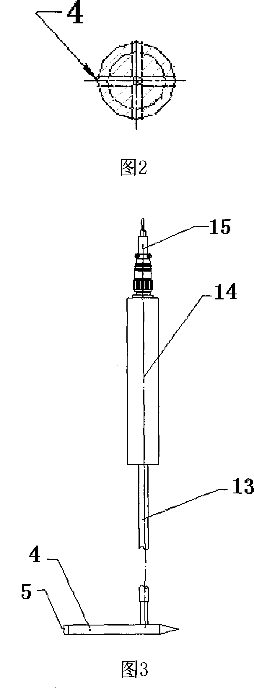
[0025] combine figure 1 , to be further described below: a flow velocity measurement sensor is composed of a Pitot tube 10, a total pressure sensor and a static pressure sensor that are respectively arranged at the front end of the Pitot tube (also known as the total pressure measuring point facing the water) and the side. The pressure sensor and the static pressure sensor are respectively composed of silicon piezoresistive sensitive components. The silicon piezoresistive sensitive component 3 in the total pressure sensor is arranged in the lumen at the front end of the Pitot tube, and is aligned with the total pressure inlet hole 5 at the front end of the lumen. Flat installation. And the silicon piezoresistive sensitive component 2 in this static pressure sensor is arranged on this Pitot tube middle lumen, and installs flush with the output nozzle 42 of the static pressure induction tube 4 in this Pitot tube, this static pressure induction tube 4. The other end is set at th...


PUM


Abstract

The invention discloses a flow rate measurement transducer which consists of an impact tube, a total-pressure transducer and a static pressure transducer which are respectively arranged at the front end and the lateral part of the impact tube. The total-pressure transducer and the static pressure transducer respectively consist of a silicon piezoresistive sensitive component which is a silicon sensitive element that is provided with Wheatstone bridge structure, and with E type island film structure, the silicon piezoresistive sensitive component in the total-pressure transducer is arranged inthe front end lumen of the impact tube and installed at the same level with a total-pressure and entrance-pressure hole at the front end of the lumen, while the silicon piezoresistive sensitive component in the static pressure transducer is arranged in the middle lumen of the impact tube and installed at the same level with the output pipe-outlet of the static-pressure and lead-pressure pipe in the impact tube, the static-pressure and lead-pressure pipe is arranged at the lateral part of the impact tube, while the tail part of the impact tube is connected with an output horizontal pipe, the signal leads of the two transducers are respectively led out through the communicated lumens of the impact tube and the output horizontal pipe and then respectively led to an output cable after passingthrough two signal conditioning circuits. The flow rate measurement transducer has one-time measurement of total pressure, static pressure, dynamic state and flow rate, and the output signal can be directly connected with the instrument for display and data processing.

Description

technical field [0001] The invention relates to a flow velocity measurement sensor, in particular to a flow velocity measurement sensor in which two miniature piezoresistive pressure sensors are installed in a standard pitot tube. Background technique [0002] At present, there are mainly pitot tubes, hot wire (or hot film) anemometers, laser Doppler current meters, and particle image velocimeters to measure the dynamic velocity of water flow. Other methods are evolved based on the basic principles of these methods. At present, the four basic flow rate measurement methods have their own characteristics and application ranges. The four methods have their own advantages and disadvantages, and it is impossible to replace each other. Pitot tube is widely used in industrial occasions because of its convenient use, high measurement accuracy and high cost performance. [0003] The traditional pitot tube type speedometer forms a stagnation point at the front end of the pitot tube, ...

Claims


Application Information

Patent Timeline
Patent Type & Authority Patents(China)
IPC IPC(8): G01P5/16G01P5/165G01L9/06
Inventor 王文襄朱金宝李水侠杨成王利强戴晓兵
Owner KUNSHAN SHUANGQIAO SENSOR MEASUREMENT CONTROLLING
Why Eureka
Try Eureka