Audio self-coupling output transformer applied in electric vibration experiment
A technology for output transformers and test systems, applied in transformers, fixed transformers, transformers/inductor coils/windings/connections, etc., can solve problems such as difficulty in reducing leakage inductance, large volume, thick wires, etc., to meet the requirements of driving voltage, The effect of wide operating frequency range and increased surface area
- Summary
- Abstract
- Description
- Claims
- Application Information
AI Technical Summary
Problems solved by technology
Method used
Image

Examples
Embodiment 1
[0039] Embodiment 1: An audio frequency autotransformer applied to an electrodynamic vibration test system
[0040] Such as Figure 5 As shown, it is mainly composed of coil winding 8 and iron core 9, wherein iron core 9 has an iron core winding post 10, and coil winding 8 is composed of one insulated wire, or two insulated wires connected in parallel.
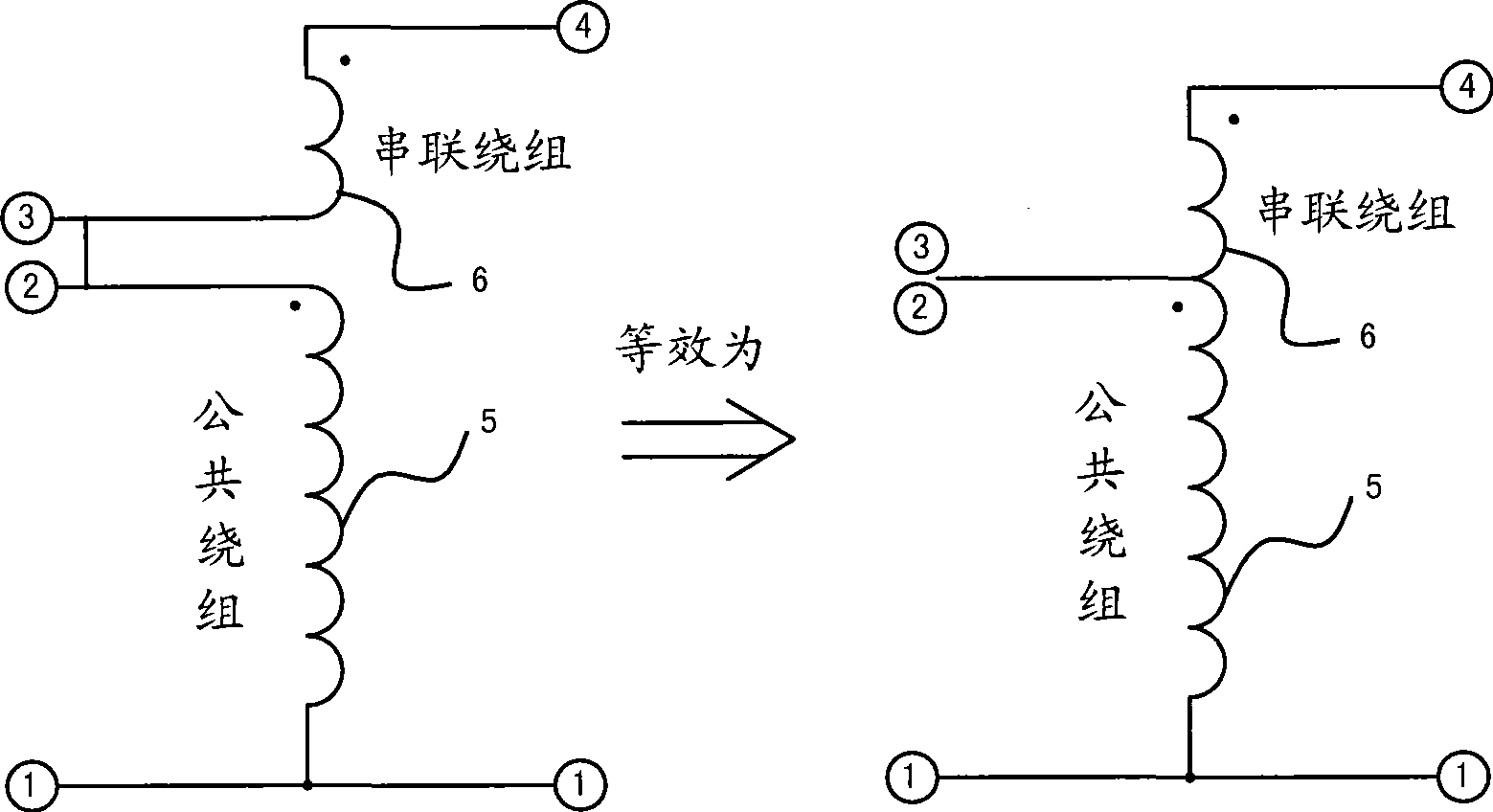
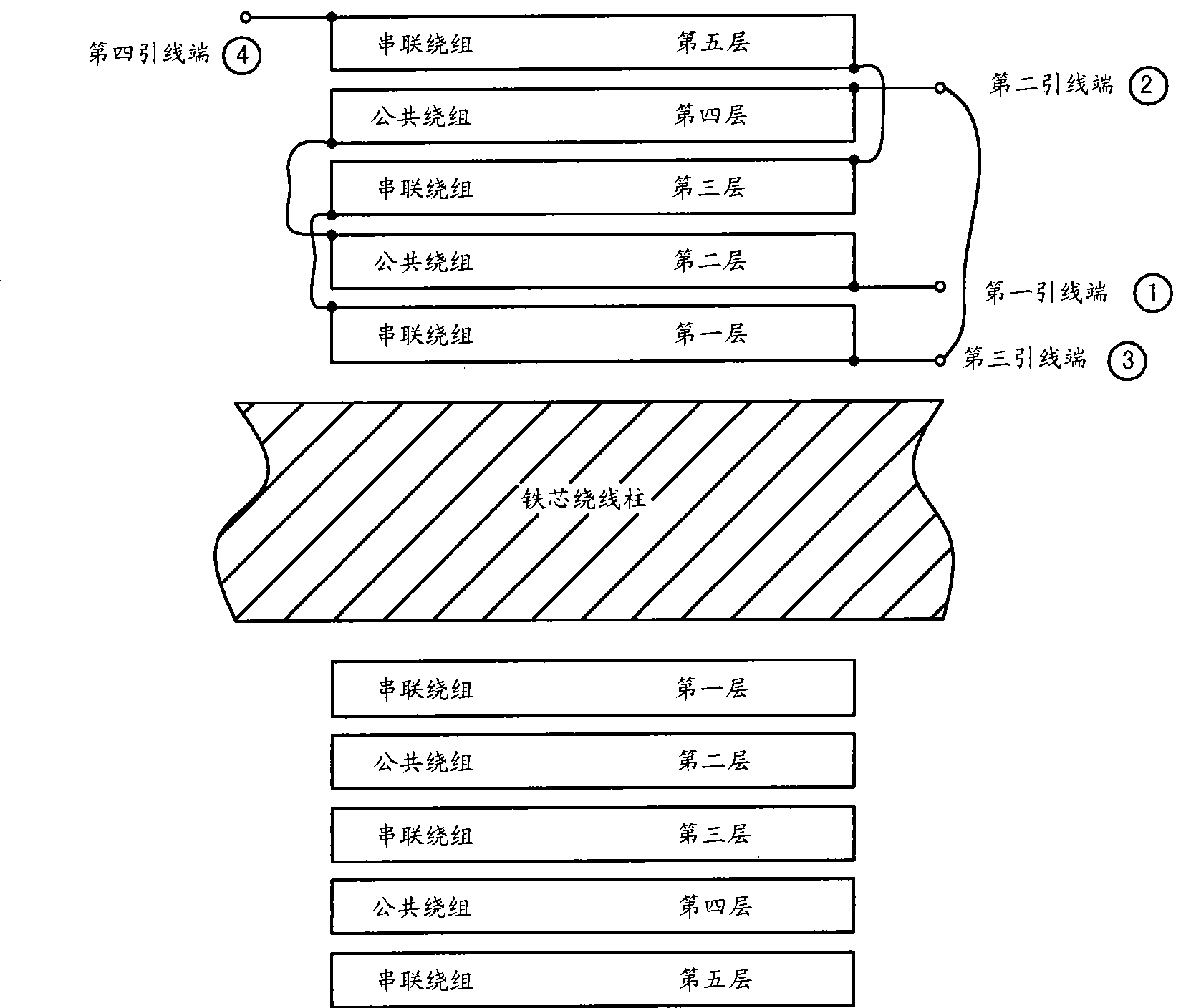
[0041] Coil winding 8 as figure 2 As shown, it consists of a common winding 5 and a series winding 6, one of the two ends of the common winding 5 is used as the first lead end 1, the other end is used as the second lead end 2, and one of the two ends of the series winding 6 is used as the third lead end 3 , and the other end is used as the fourth lead terminal 4. Winding structure such as image 3 As shown, taking the central axis of the winding post 10 as the reference, the series winding 6 is wound and distributed in the first, third, and fifth odd-numbered layers from the inside to the outside of the winding post 10 of ...
Embodiment 2
[0044] Embodiment 2: An audio frequency autotransformer output transformer applied to an electrodynamic vibration test system
[0045] Such as Figure 8 As shown, one of the two ends of the common winding 5 is used as the first lead end 1, and the other end is used as the second lead end 2, and one end of the two ends of the series winding 6 is used as the third lead end 3, and the other end is used as the fourth lead end 4 . The winding structure is based on the central axis of the winding post 10, and the common winding 5 is wound and distributed on the first, third, and fifth odd-numbered layers in the radial direction of the winding post 10 of the iron core from the inside to the outside, where the first lead Terminal 1 is located at the end of the first layer, and the second lead terminal 2 is located at the end of the fifth layer. The series winding 6 is wound and distributed on the second and fourth even-numbered layers from the inside to the outside in the radial dir...
Embodiment 3
[0047] Embodiment 3: An audio frequency autotransformer output transformer applied to electrodynamic vibration test system
[0048] Such as Figure 9 As shown, one of the two ends of the common winding 5 is used as the first lead end 1, and the other end is used as the second lead end 2, and one end of the two ends of the series winding 6 is used as the third lead end 3, and the other end is used as the fourth lead end 4 . The winding structure is based on the central axis of the winding post 10, and the common winding 5 is wound on the first and third odd-numbered layers from the inside to the outside in the radial direction of the winding post 10 of the iron core, where the first lead end 1 is located at At the end of the first layer, the second lead terminal 2 is located at the end of the third layer. The series winding 6 is wound and distributed on the second even-numbered layer from the inside to the outside in the radial direction of the winding post 10 of the iron cor...
PUM
 Abstract
Description
Claims
Application Information
 - R&D Engineer
- R&D Manager
- IP Professional
- Industry Leading Data Capabilities
- Powerful AI technology
- Patent DNA Extraction
Browse by: Latest US Patents, China's latest patents, Technical Efficacy Thesaurus, Application Domain, Technology Topic.
© 2024 PatSnap. All rights reserved.Legal|Privacy policy|Modern Slavery Act Transparency Statement|Sitemap