Surface mounting process for flexible circuit board and used magnetic tool and steel mesh

A surface mount technology and flexible circuit board technology, which is applied in the direction of assembling printed circuits with electrical components, can solve problems affecting the quality of the mounting process, affecting the SMT and reflow soldering process, and having too much solder paste to achieve good isolation Thermal effect, saving of tool cost and labor cost, effect of quality improvement

Active Publication Date: 2009-03-11
东莞市贞观盛智控科技有限公司
View PDF5 Cites 91 Cited by
  • Summary
  • Abstract
  • Description
  • Claims
  • Application Information

AI Technical Summary

Problems solved by technology

[0007] Since the cover plate is used to cover the FPC, a layer of stencil needs to be set on the cover plate when solder paste is printed, and the cover plate has a certain thickness. If the screen is di

Method used


Image

  • Surface mounting process for flexible circuit board and used magnetic tool and steel mesh
  • Surface mounting process for flexible circuit board and used magnetic tool and steel mesh
  • Surface mounting process for flexible circuit board and used magnetic tool and steel mesh

Examples


Embodiment 1

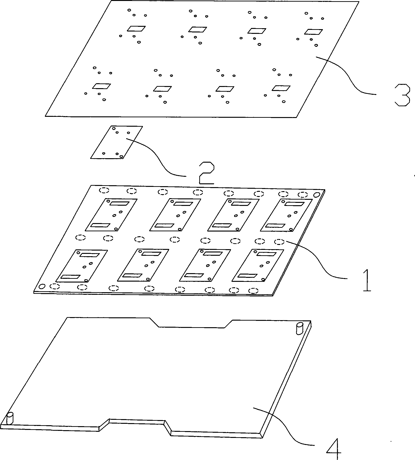
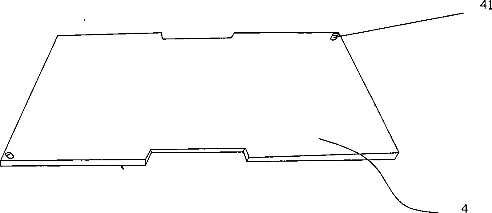
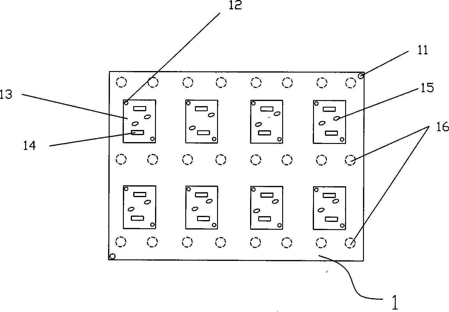
[0041] Such as Figure 1-5 As shown, the magnetic jig involved in the present invention includes a magnetic tray 1, a snap cover 3 and a positioning base 4, and the positioning base 4 is provided with two positioning pins 41 (three or more than three positioning pin); the magnetic tray 1 is made of aluminum alloy blackened and then inlaid with a permanent magnet 16 resistant to a high temperature of 300°C made), the magnetic tray 1 is provided with a base positioning hole 11 corresponding to the base positioning pin 41 and a tray positioning hole 12, and the magnetic tray 1 is also provided with a positioning groove with the same shape as the flexible circuit board 2 13. The groove 14 and the heat dissipation hole 15 corresponding to the position of the components on the circuit board, the groove 14 can be filled with components when the flexible circuit board 2 is mounted on both sides; the press button cover Plate 3 is a stainless steel sheet that can be attracted by a magn...

Embodiment 2

[0050] Such as Figure 1-5 As shown, the magnetic jig involved in the present invention includes a magnetic tray 1, a snap cover 3 and a positioning base 4, and the positioning base 4 is provided with two positioning pins 41 (three or more than three alignment pin); the magnetic tray 1 is made of blackened aluminum alloy and then inlaid with a permanent magnet resistant to 300°C high temperature (also can be made of synthetic stone, high temperature resistant glass fiber and inlaid with a high temperature resistant permanent magnet ), the magnetic tray 1 is provided with a base positioning hole 11 corresponding to the base positioning pin 41 and a tray positioning hole 12, and the magnetic tray 1 is also provided with a positioning groove 13 having the same shape as the flexible circuit board 2 1. The groove 14 and the heat dissipation hole 15 corresponding to the position of the components on the circuit board, the groove 14 can be filled with components when the flexible cir...


PUM

PropertyMeasurementUnit
Thicknessaaaaaaaaaa
Depthaaaaaaaaaa
Thicknessaaaaaaaaaa

Abstract

The invention relates to the manufacturing technology of printed wiring board, in particular to a flexible printed circuit (FPC) surface mount technology (SMT) as well as a magnetic tool and a steel mesh which are used for the FPCSMT. The magnetic tool comprises a buckle cover board and a magnetic carrying tray, wherein the magnetic carrying tray is a magnetic baseplate, the buckle cover board is a metal sheet which can be attracted by the magnetic baseplate, and the buckle cover board is provided with a slotted hole used for the solder paste printing and the surface mounting of a FPC. The invention is characterized in that the buckle cover board is a steel sheet which can be attracted by the magnetic baseplate, the step layer which is the same as the buckle cover board in shape is etched on the magnetic carrying tray, the depth of the step layer is the same as the thickness of the steel sheet; before the circuit board printing, the magnetic carrying tray is fixed on a positioning base, and then the FPC and the buckle cover board are arranged on the magnetic carrying tray; after the accurate positioning, the FPC and the magnetic tool are taken down the positioning base to conduct the solder paste printing process, the surface mounting process and the reflow soldering process.

Description

【Technical field】 [0001] The invention relates to the manufacturing technology of printed circuit boards, in particular to a surface mounting process of flexible circuit boards and magnetic jigs and steel nets used in the process. 【Background technique】 [0002] Flexible printed circuit (FPC) has the characteristics of high wiring density, light weight, and thin thickness. It is mainly used in many products such as mobile phones, notebook computers, PDAs, and digital cameras. The surface mount technology (SMT) process of flexible circuit board mainly includes three basic links of solder paste printing, placement and reflow soldering. Solder paste printing refers to the printing of solder paste on the pads of the circuit board through the template of the predetermined pattern; patch is to accurately install the surface mount components on the fixed position of the flexible circuit board; reflow soldering refers to melting the solder paste to make the electronic Mechanical an...

Claims


Application Information

Patent Timeline
IPC IPC(8): H05K3/34C22C38/58C22C38/40
Inventor 林克治
Owner 东莞市贞观盛智控科技有限公司
Why Eureka
Try Eureka