
System parameter of linearity multi-port, detection method and device for vector network analyzer

A technology for system parameters and measurement methods, which is applied in measuring devices, instruments, measuring electrical variables, etc., and can solve problems such as time-consuming processing and complex structure.

Active Publication Date: 2009-03-18
矢加部 利幸
View PDF5 Cites 14 Cited by
  • Summary
  • Abstract
  • Description
  • Claims
  • Application Information

AI Technical Summary

Problems solved by technology

In the principle of the integral correction method, it is necessary to set a phase shifter on the VNA, which makes the structure complicated
In addition, when calculating system parameters, Fourier transform is performed, so it still takes time to process

Method used

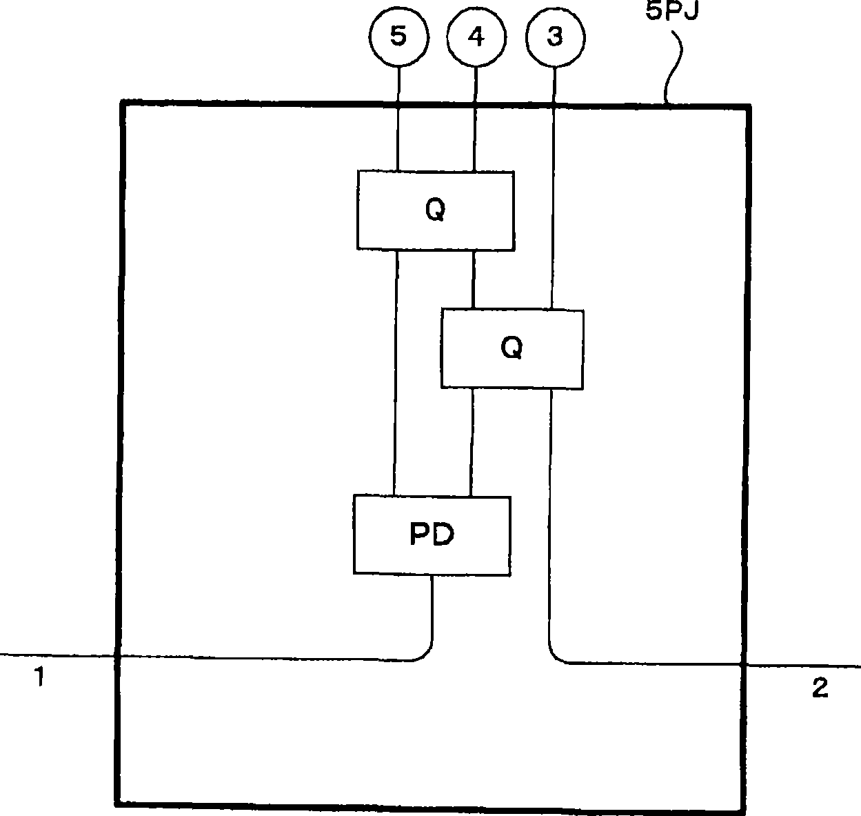
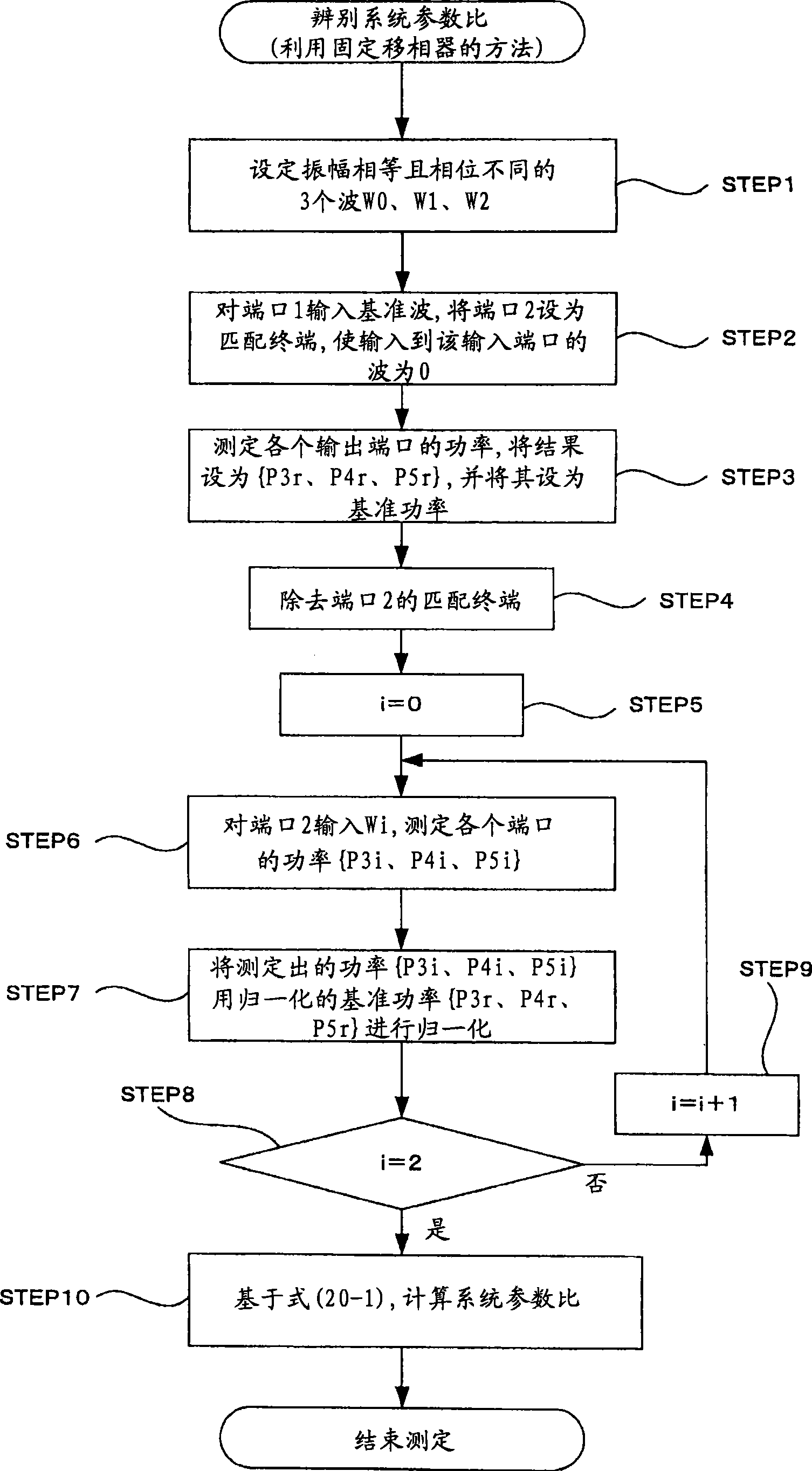
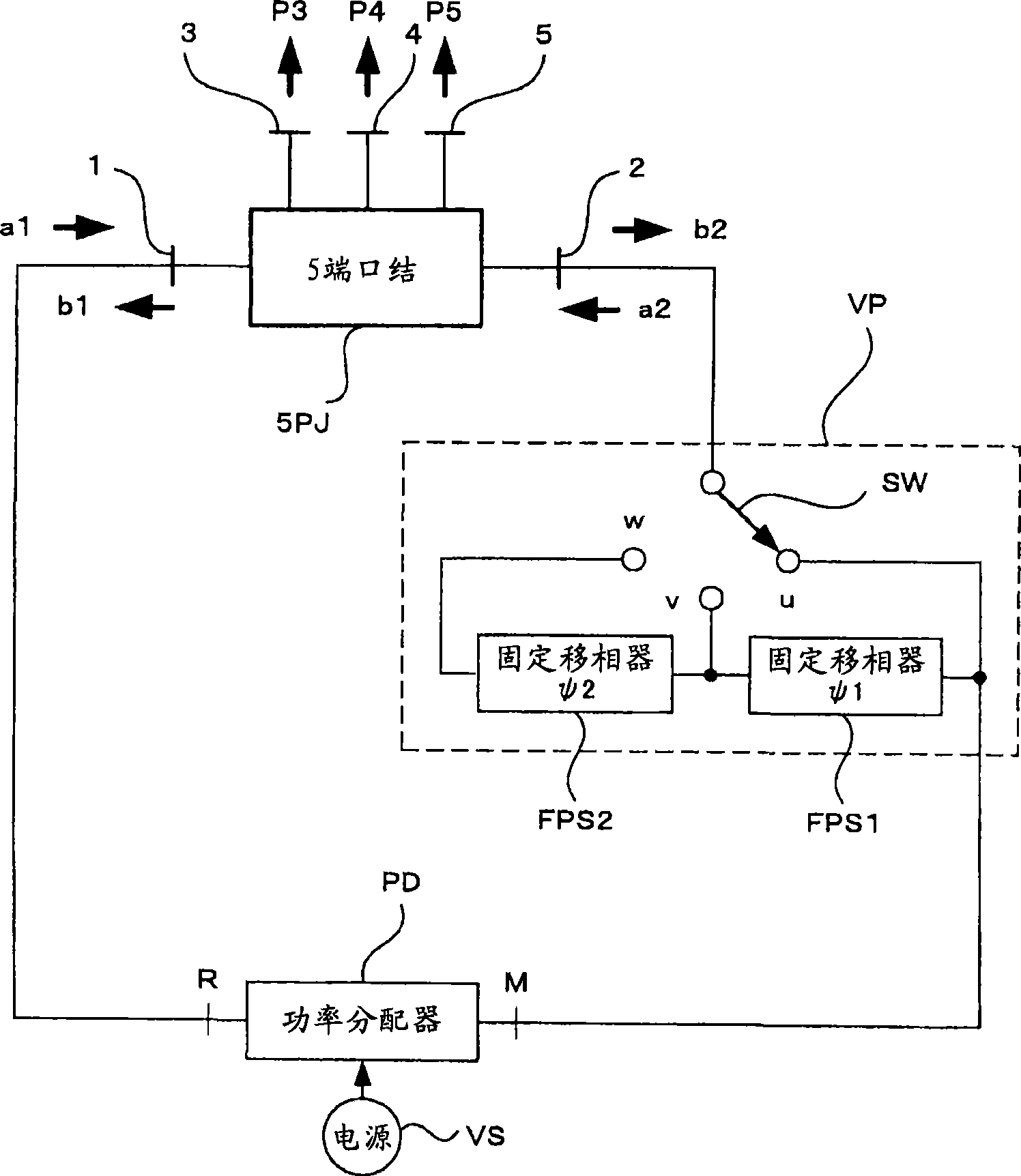

Image

  • System parameter of linearity multi-port, detection method and device for vector network analyzer
  • System parameter of linearity multi-port, detection method and device for vector network analyzer
  • System parameter of linearity multi-port, detection method and device for vector network analyzer

Examples


Embodiment Construction

[0108] Hereinafter, the description will be made in the following order.

[0109] 1. Measurement method of system parameters

[0110] 1.1 The method of measuring the system parameters of the correlator using the 5-port junction

[0111] 1.2 The method of measuring the system parameters of the correlator using a 5-port junction (integration method)

[0112] 1.3 The method of measuring the system parameters of the correlator using the 6-port junction

[0113] 1.4 The method of measuring the system parameters of the reflector using the N-port junction

[0114] 2. Measurement method of DUT

[0115] 2.1 VNA using a 5-port correlator and the measurement method using the VNA

[0116] 2.1.1 Description of the measurement system

[0117] 2.1.2 Description of the measurement procedure of the S-parameter of the DUT

[0118] 2.2 VNA using a 6-port correlator and the measurement method using the VNA

[0119] 3. The measurement theory of this application

[0120] 3.1 5-port correlator

[0121] ...


PUM


Abstract

The invention aim to shorten computing time used for system parameters of a five-port knot or a six-port knot e.g. a network analyzer (VNA), thereby simplifying a structure of a tested circuit. VNA is used to test the system parameters required by a tested device (DUT), but in the prior art, the system parameters are computed according to positions and diameters of centers of three circles on a complex plate based on complex amplitude ratio of input ports W=a2 / a1, just like the known integration method, complex steps are needed. The invention performs computation based on points of intersection of three circles of the system parameter k on the complex plane, e.g. three waves with phase difference 120 degrees are input in turn to input ports of the five-port knot, power values are output normalizedly based on the preset reference power, to compute the system parameters. Compared with the integration method in the prior, computation is simple, and no phase shifter is required.

Description

Technical field [0001] The present invention relates to a technique for measuring the amplitude ratio and phase difference of signals in the high frequency region (especially the microwave band, millimeter wave band, submillimeter wave band) or (infrared, visible light, ultraviolet). Background technique [0002] For the research and development of equipment, circuits, or equipment that operate in the high-frequency region, it is essential to measure the phase difference between the input and output signals of the equipment, circuit, or equipment. In the past, VNA (Vector Network Analyzer: Vector Network Analyzer) completed this task. The VNA is a device used to measure the amplitude ratio and phase difference (S parameter: scattering matrix element) of the incident wave and the reflected wave, or the incident wave or the transmitted wave of the DUT (Device Under Test). [0003] [Patent Document 1] US Patent No. 4,104,583: A six-port reflector (Six-Port-Reflectometer) is disclose...

Claims


Application Information

Patent Timeline
IPC IPC(8): G01R27/28G01R25/00
Inventor 矢加部利幸矢部初男近藤昭治肖凤超高桥圭山田恭一
Owner 矢加部 利幸
Learn More