Radially staged microscale turbomolecular pump

A turbomolecular and rotor technology, applied in the design and manufacture of small turbomolecular vacuum pumps, can solve problems such as difficult pumping volumes

Inactive Publication Date: 2009-03-25
HONEYWELL INT INC
View PDF0 Cites 6 Cited by
  • Summary
  • Abstract
  • Description
  • Claims
  • Application Information

AI Technical Summary

Problems solved by technology

[0004] Attempts to create portable vacuum pumps have had limited success because of the difficulty in achieving the desired pumping volume in a compact pump design

Method used


Image

  • Radially staged microscale turbomolecular pump
  • Radially staged microscale turbomolecular pump
  • Radially staged microscale turbomolecular pump

Examples


Embodiment Construction

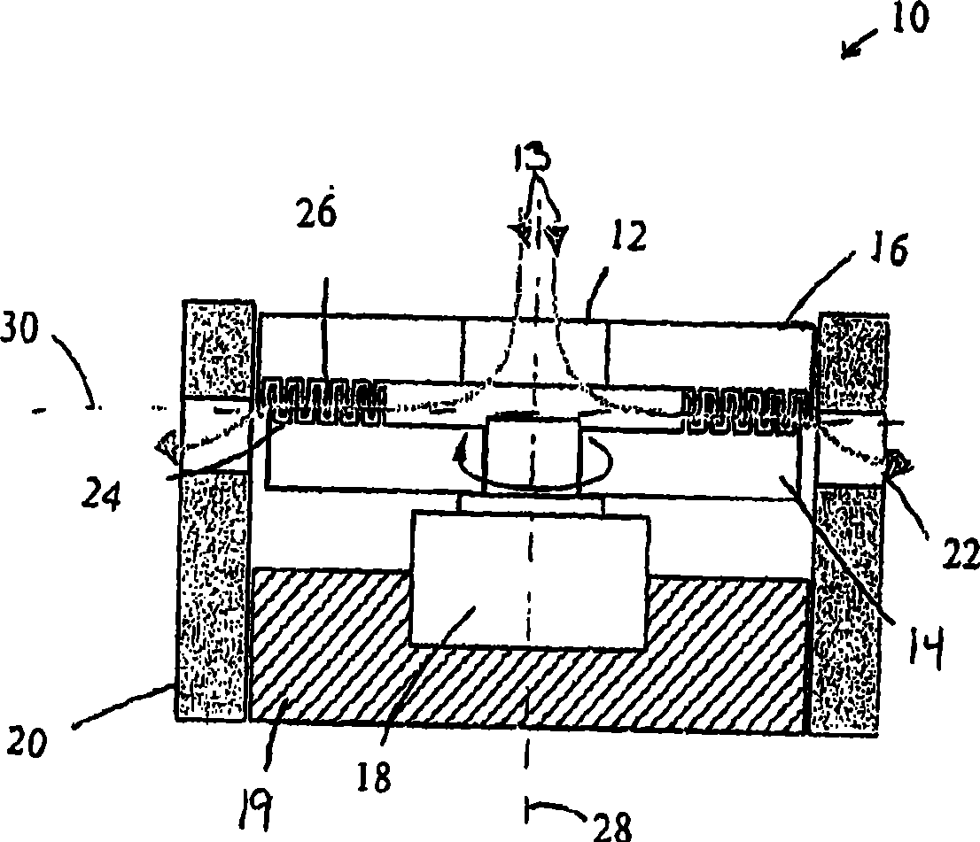
[0015] figure 1 An example diagram of a turbomolecular pump 10 showing radial flow. The pump 10 includes an inlet 12 , a rotor 14 , a stator 16 , a motor 18 , a housing 20 and a plurality of outlets 22 . The rotor 14 includes a plurality of rotor blades 24 . The stator 16 includes a plurality of stator slots 26 .

[0016] Housing 20 surrounds rotor 14 and stator 16 . Motor mount 19 holds motor 18 in place and aligns motor 18 with rotor 14 and stator 16 . The inlet 12 is used to allow a quantity of gas 13 to enter the housing 20 and flow into the rotor 14 .

[0017] Each slot of the plurality of stator slots 26 is positioned to receive each blade of the plurality of rotor blades 24 . In the assembled state, the stator 16 is fixed and the rotor 14 is free to rotate.

[0018] The peripheral speed of the rotor can be from 10 to 300m / s, depending on the required compression ratio and air flow. Rotation of the rotor 14 relative to the stator 16 causes gas to be pumped radiall...


PUM


Abstract

A radial turbomolecular vacuum pump that includes a rotor made from a silicon rotor surface comprising monolithically fabricated micro blades, and a stator made from a silicon stator surface comprising corresponding monolithically fabricated grooves. The micro blades and grooves are arranged in multiple rings, and the rotor and stator disks are placed in proximity, creating interdigitated stator and rotor blade rings. The interdigitated stator and rotor blade rings form a multi-stage compression in the radial direction.

Description

technical field [0001] The present invention relates generally to the field of vacuum pumps. More particularly, the present invention relates to the design and manufacture of small turbomolecular vacuum pumps. Background technique [0002] A turbomolecular pump is a vacuum pump used to obtain and maintain a high vacuum. Conventional turbomolecular pumps are capable of high vacuum levels and pump speeds. However, conventional turbomolecular pumps are too bulky for most portable applications, such as those used with micro-instruments. For example, rotor diameters are typically sized greater than 75 millimeters, which results in turbomolecular pumps that are inconveniently large for portable applications. [0003] In addition, conventional turbomolecular pumps are only capable of operating at fairly low exhaust pressures, typically less than 10 mTorr, and a first-stage or foreline inline pump must be used between the turbomolecular pump exhaust and the atmosphere. It is dif...

Claims


Application Information

Patent Timeline
Patent Type & Authority Applications(China)
IPC IPC(8): F04D19/04F04D29/38F04D29/52
CPCB81B2203/056B81B2201/036B81B3/0021F04D17/168F04D17/127B81B2201/034
Inventor W·杨
Owner HONEYWELL INT INC
Why Eureka
Try Eureka