Partial gating glimmer detector of image intensifier based on generation III proximity type at normal temperature

A technology of image intensifier and detector, which is applied in the field of low-light detectors, can solve problems affecting imaging quality, electron accumulation, etc., and achieve the effects of reducing escape probability, clear imaging, and normal operation

Inactive Publication Date: 2010-04-07
XIAN UNIV OF TECH
View PDF5 Cites 0 Cited by
  • Summary
  • Abstract
  • Description
  • Claims
  • Application Information

AI Technical Summary

Problems solved by technology

[0005] However, in terms of improving the detection limit, although the various devices researched and developed above have the effect of strengthening and multiplying the electrons generated by the image intensifier, they have not been able to effectively accumulate the electrons, but only use the CCD to detect the photon signal. long-term accumulation, therefore, the performance of the CCD is largely limited by the low-light detection limit by 10 -6 lx increased to 10 -8 lx; and in the realization of strong light detection, the existing detectors are all gating as a whole, which is equal to or greater than 10 for a certain area 5 lx too strong light can not be controlled locally, which affects the image quality

Method used


Image

  • Partial gating glimmer detector of image intensifier based on generation III proximity type at normal temperature
  • Partial gating glimmer detector of image intensifier based on generation III proximity type at normal temperature
  • Partial gating glimmer detector of image intensifier based on generation III proximity type at normal temperature

Examples


Embodiment Construction

[0028] The present invention will be described in detail below in conjunction with the accompanying drawings and specific embodiments.

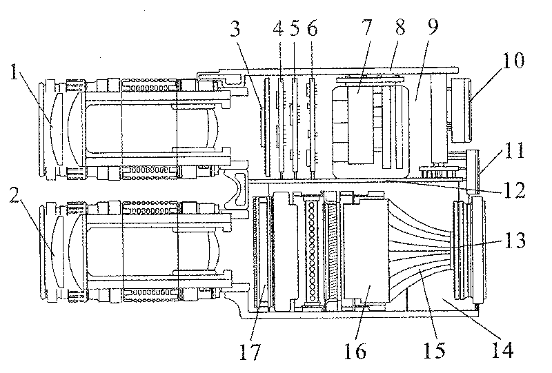
[0029] The structure of the detector of the present invention, such as figure 1 shown. Including a hollow detector housing 8, the detector housing 8 is divided into a cavity A9 and a cavity B14 through a partition 12, and a photometric CCD3, a video acquisition module 4, and a field programmable gate array 5 are sequentially arranged in the cavity A9 , a liquid crystal drive module 6, a power supply 7 and a display screen 10, a lens A1 is arranged on the outside of the cavity A9 connected to the photometering CCD3, a button 11 is arranged on the outside of the other end of the cavity A9, and a button 11 is arranged on the outside of the cavity B14. Liquid crystal panel 17, magnetic mirror array image intensifier 16, fiber optic cone 15 and imaging CCD13, lens B2 is arranged on the end of the cavity A9 outside which is connected with liquid c...


PUM


Abstract

The invention discloses a low light level detector which is based on a third generation proximity image intensifier and performs local gating at normal temperature. The low light level detector comprises a detector shell, wherein the detector shell is divided into an upper cavity and a lower cavity; a light measurement CCD, a video acquisition module, a field programmable gate array, a liquid crystal driving module, a power supply and a display screen are sequentially arranged in the upper cavity; one end, which is connected with the light measurement CCD, outside the upper cavity is providedwith a lens A; a pushbutton is arranged outside the other end of the upper cavity; a liquid crystal board, a third generation proximity type magnetic mirror array image intensifier, an optical fiber taper and an imaging CCD are sequentially arranged in the lower cavity; one end, which is connected with the liquid crystal board, outside the lower cavity is provided with a lens B; and the lens A andthe lens B are parallelly arranged. The detector automatically performs local gate control on light intensity, has wider dynamic application range, and can normally work and clearly image within thelight intensity range of between 10<-8> and 10<5>lx.

Description

technical field [0001] The invention belongs to the technical field of photoelectric imaging detection, and relates to a low-light detector, in particular to a low-light detector based on a third-generation proximity image intensifier and partially gating at normal temperature. Background technique [0002] Low-light night vision technology is widely used in transportation, television, communications, medicine and health, military and other fields. After nearly 30 years of rapid development, how to improve the dynamic range of low-light imaging system detection has become an important topic in this field, and the key to solving this problem lies in how to improve the low-light detection limit and how to perform normal imaging under strong light without damaging the detector. [0003] In terms of improving the low-light detection limit, foreign countries have developed a detection limit of 10 -9 CCD (charge coupled device) camera with lx illuminance, German B&M Spectrum Com...

Claims


Application Information

Patent Timeline
Patent Type & Authority Patents(China)
IPC IPC(8): G01J1/42G01J1/04
Inventor 唐远河杨旭三刘锴刘汉臣张瑞霞郜海阳赵高翔叶娜梁元李卿
Owner XIAN UNIV OF TECH
Why Eureka
Try Eureka