Backlight module and LCD using the backlight module

A liquid crystal display and backlight module technology, applied in optics, light sources, instruments, etc., can solve the problems of reducing light use efficiency and increasing production cost, and achieve the effect of reducing production cost and improving light use efficiency

Inactive Publication Date: 2009-03-25
NANO PRECISION
View PDF0 Cites 12 Cited by
  • Summary
  • Abstract
  • Description
  • Claims
  • Application Information

AI Technical Summary

Problems solved by technology

However, increasing the precision of the surface mount technology will increase the production cost, and increasing the distance between the light incident surface 112 of the light guide plate 110 and the LED packaging structures 124 will reduce the light use efficiency.

Method used


Image

  • Backlight module and LCD using the backlight module
  • Backlight module and LCD using the backlight module
  • Backlight module and LCD using the backlight module

Examples


Embodiment Construction

[0015] The following descriptions of various embodiments refer to the accompanying drawings to illustrate specific embodiments in which the present invention can be practiced. The direction terms mentioned in the present invention, such as "up", "down", "front", "rear", "left", "right", etc., are only referring to the directions of the drawings. Accordingly, the directional terms are used to illustrate, not to limit, the invention.

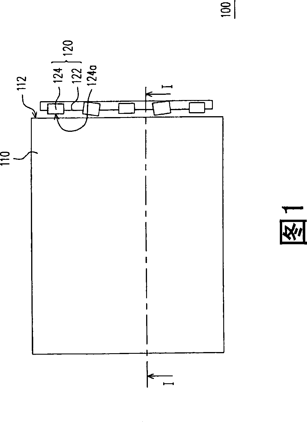
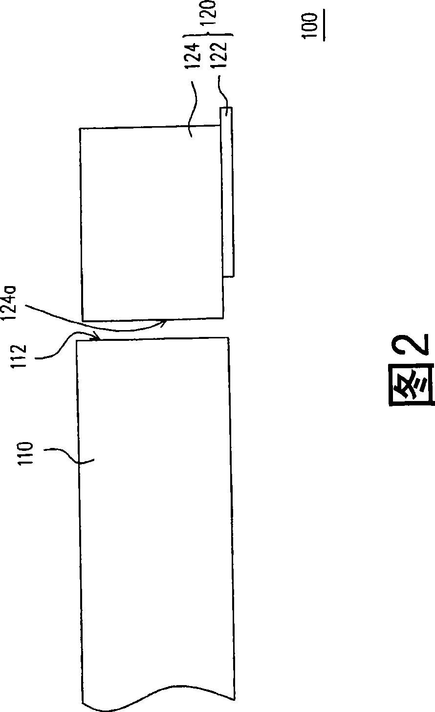
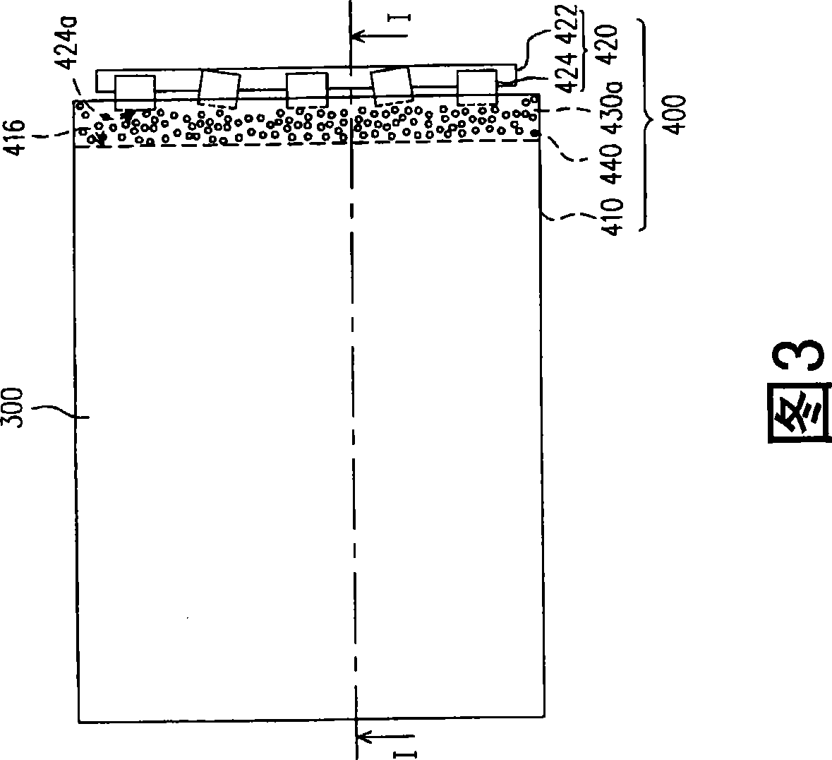
[0016] FIG. 3 is a schematic top view of a liquid crystal display according to an embodiment of the present invention, and FIG. 4 is a schematic cross-sectional view of the liquid crystal display of FIG. 3 along line I-I. As shown in FIGS. 3 and 4 , the liquid crystal display 200 includes a liquid crystal display panel 300 and at least one backlight module 400 . The backlight module 400 is, for example, a side type BLM, which is disposed on one side of the liquid crystal display panel 300 and includes a light guide plate 410 , a light source 420 ...


PUM


Abstract

The invention discloses a backlight module, which comprises a light guide plate, a light source and a light transmission elastic body. The light guide plate is provided with a first light emitting surface, a bottom surface opposite to the first light emitting surface and at least one light incident surface contacted with the first light emitting surface and the bottom surface. The light source is arranged beside the light incident surface and comprises a circuit board and a plurality of LED devices. Each LED device is suitable for emitting the light penetrating through the light incident surface and is electrically connected to the circuit board. The light transmission elastic body is arranged between the light incident surface and the LED devices.

Description

technical field [0001] The invention relates to a backlight module, and in particular to a liquid crystal display using the backlight module. Background technique [0002] FIG. 1 is a schematic top view of a conventional backlight module, and FIG. 2 is a partially enlarged cross-sectional schematic diagram of the backlight module of FIG. 1 along line I-I. As shown in FIGS. 1 and 2 , the backlight module 100 includes a light guide plate 110 and a light source 120 disposed beside the light incident surface 112 of the light guide plate 110 . The light source 120 includes a circuit board 122 and a plurality of LED packaging structures 124 assembled on the circuit board 122 by surface mount technology (SMT). Each LED packaging structure 124 has a light emitting surface 124 a facing the light incident surface 112 . [0003] It should be noted that when the LED packaging structures 124 are assembled to the circuit board 122 , the light emitting surfaces 124 a will not be on the s...

Claims


Application Information

Patent Timeline
Patent Type & Authority Applications(China)
IPC IPC(8): G02F1/13357F21K7/00G02F1/1335F21K99/00
Inventor 陈建翔刘明达饶瑞年
Owner NANO PRECISION
Why Eureka
Try Eureka