
Boost circuit modeling approach and use thereof based on finite state machine

A finite state machine and modeling method technology, applied in the field of power electronics technology and hybrid systems, can solve problems such as inability to accurately obtain motion laws, and achieve the effects of simple structure, high conversion efficiency, and small size

Inactive Publication Date: 2009-03-25
TIANJIN UNIVERSITY OF TECHNOLOGY
View PDF0 Cites 19 Cited by
  • Summary
  • Abstract
  • Description
  • Claims
  • Application Information

AI Technical Summary

Problems solved by technology

It is only effective for slowly changing signals, and there is a large deviation between the high-frequency switching state and the actual situation; it can only understand the performance of the converter macroscopically, and cannot accurately obtain its motion law

Method used


Image

  • Boost circuit modeling approach and use thereof based on finite state machine
  • Boost circuit modeling approach and use thereof based on finite state machine
  • Boost circuit modeling approach and use thereof based on finite state machine

Examples


Embodiment

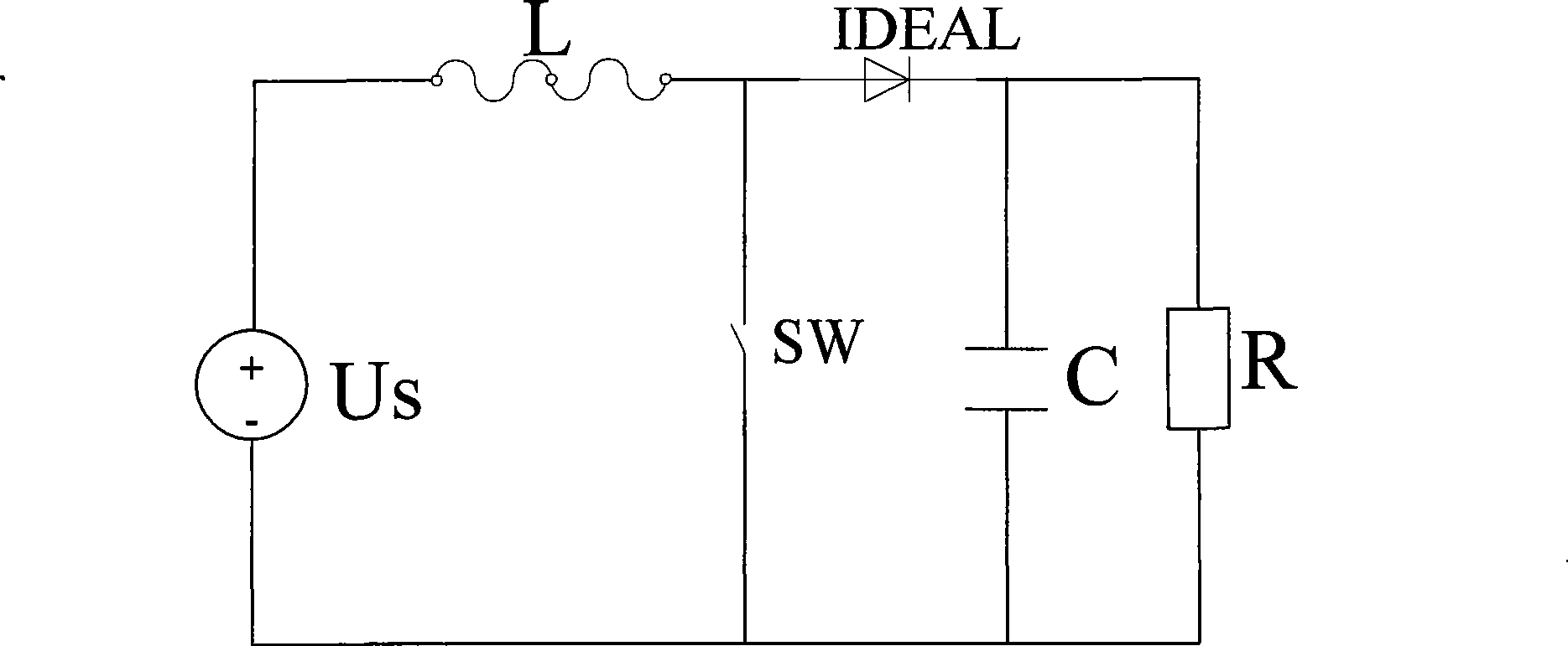
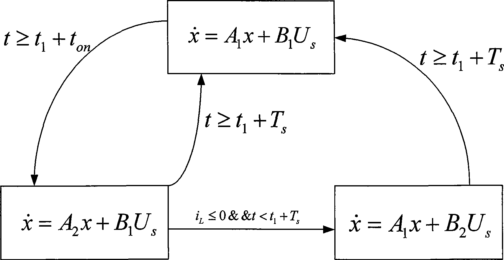
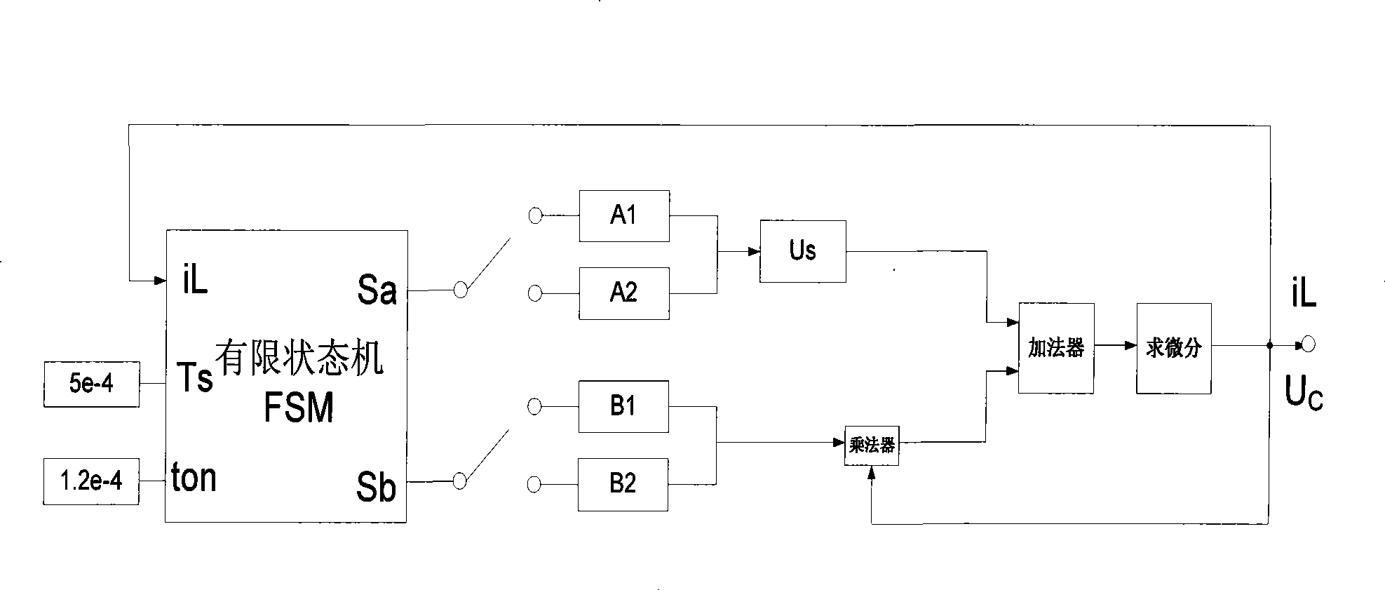
[0031] Embodiment: a kind of Boost circuit modeling method based on finite state machine (see attached figure 1 , 2 , 3), it is characterized in that it comprises the following working steps:

[0032] (1) Analyze the Boost main circuit, determine the working state of the system, and obtain the number of working states;

[0033] (2) Determine the transition conditions between the various working states of the Boost circuit, so as to determine the discrete events of the system;

[0034] (3) Determine the state variables, input variables, and output variables of the system, and establish the state equation and output equation of the Boost circuit;

[0035] (4) Determine the input matrix, state matrix and output matrix of the system according to the circuit parameters;

[0036] (5) Establish the model of Boost circuit by using finite state machine.

[0037] Boost circuit (see attached figure 1 ) is composed of a constant voltage source, an energy storage inductor, a filter ca...


PUM


Abstract

The invention provides a finite state machine-based Boost circuit modeling method and application thereof. The modeling method is characterized by comprising the following steps: (1) determining the number of operational states; (2) determining conversion conditions among the operational states; (3) establishing a mathematical equation; (4) determining a matrix according to parameters; and (5) building a model. The modeling method has the advantages that the Boost circuit model built by using the finite state machine is very precise and is easy to analyze the control characteristics of a system, especially a plurality of complicated characteristics caused by the switching of a switch in a converter system. The Boost circuit has the advantages of small volume, simple structure, high conversion efficiency and so on.

Description

(1) Technical field: [0001] The invention relates to a modeling method of a Boost circuit and an application thereof, in particular to a modeling method of a Boost circuit based on a finite state machine (finite state machines, FSM) and an application thereof, and belongs to the field of power electronics technology and hybrid systems. (two) background technology: [0002] The hybrid system that has appeared in recent years has made it possible to study the control theory of power electronic circuits, and also provides many new solutions for the modeling of power electronic systems, such as automaton model, hybrid Petri net model, switching system model, hybrid logic dynamic system model Wait. [0003] From the perspective of system working characteristics, the power electronic circuit is a typical hybrid dynamic system. Due to the existence of switching devices, it has a variety of operating modes. Different operating modes correspond to different circuit topologies. The d...

Claims


Application Information

Patent Timeline
IPC IPC(8): G06F17/50
Inventor 马幼捷陈德树周雪松田密郭润睿王辉
Owner TIANJIN UNIVERSITY OF TECHNOLOGY
Learn More