Unlock instant, AI-driven research and patent intelligence for your innovation.
Self-propelled travelling-crane feeding system for H shaped cage system
What is Al technical title?
Al technical title is built by PatSnap Al team. It summarizes the technical point description of the patent document.
A feeding system and feeding technology, applied in the application, poultry industry, animal husbandry and other directions, can solve the problems of wire rope breakage, motor damage to power, affecting normal use, etc.
Active Publication Date: 2013-03-06
广州市华南畜牧设备有限公司
View PDF0 Cites 1 Cited by
Summary
Abstract
Description
Claims
Application Information
AI Technical Summary
This helps you quickly interpret patents by identifying the three key elements:
Problems solved by technology
Method used
Benefits of technology
Problems solved by technology
[0012] First, during the process of pulling and feeding the traveling frame, the wire rope is broken due to friction and needs to be replaced frequently, which affects normal use
[0013] Second, when a certain infrared detection device fails, it will cause the traction and feeding traveling frame to move to the end of the feeding trough and stop after being blocked, the motor will continue to rotate and pull the wire rope, resulting in motor damage and unnecessary power consumption loss
Method used
Image
Click on the blue label to locate the original text in one second.
Reading with bidirectional positioning of images and text.
Examples
Embodiment 1
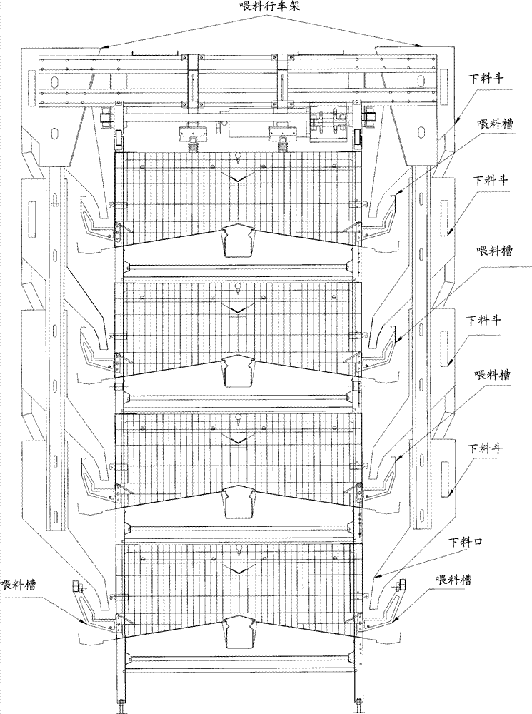
[0038] The H-type cage system is composed of multiple layers of parallel cages. Parallel feeding troughs (not shown in the figure) are arranged on both sides of the cage system. Each feeding trough is used to feed the birds in each layer of cages. feed.
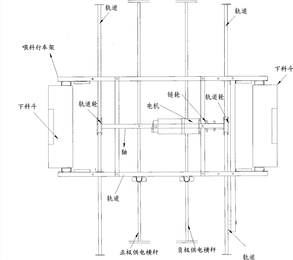
[0039] see figure 1 , The crane feeding system that is used for the H type cage system of the present embodiment comprises: the feeding truck frame, and the track parallel to the feeding trough (not shown in the figure). Wherein, the feeding carriage is provided with at least one lower hopper, and each lower hopper is connected, like this, feed can be added at the uppermost lower hopper, and the feed is shunted to each lower hopper due to the effect of gravity.
[0040] The feeding openings of each lower hopper are respectively located above each feeding trough, so that the feed added to the uppermost lower hopper of the feeding carriage flows to the lower hoppers of each layer, and is added to each feeding trough through th...
Embodiment 2
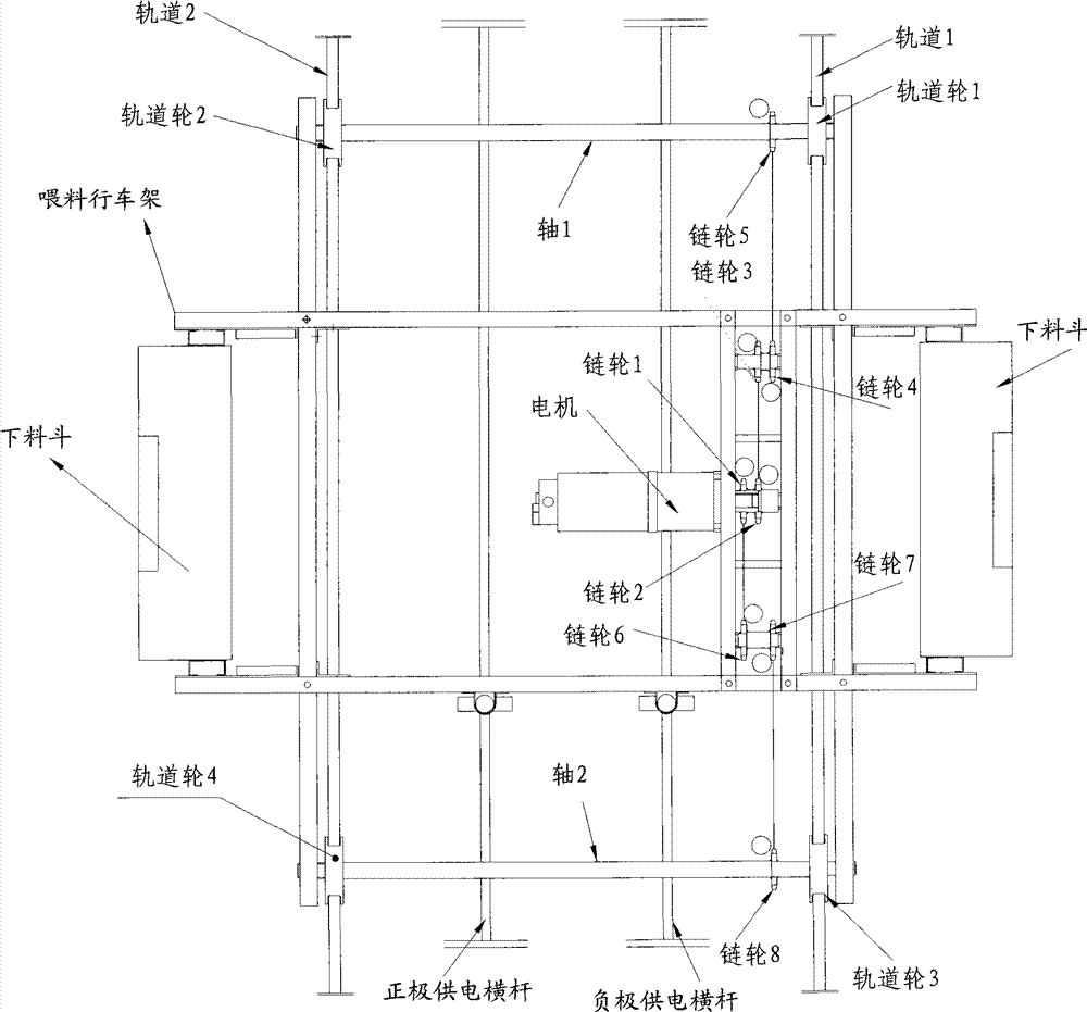
[0056] This embodiment provides another self-propelled driving feeding system, see figure 2 , 3 , this system differs from Embodiment 1 in that:
[0057] The motor is connected coaxially with the first sprocket set (sprocket 1 and sprocket 2 connected coaxially). The motor drives the first sprocket set (sprocket 1, sprocket 2) to rotate.
[0058] A second sprocket set (coaxially connected sprocket 3, sprocket 4) and a third sprocket set (coaxially connected sprocket 6, sprocket 7) are respectively arranged on both sides of the first sprocket set. And sprocket 1, sprocket 3 are connected by hinge, and sprocket 2, sprocket 4 are connected by hinge.
[0059] On the outside of the second sprocket set and the third sprocket set, shafts 1 and 2 are also arranged, and sprocket 5 , track wheel 1 and track wheel 2 are fixedly arranged on shaft 1 . Track wheel 1, track wheel 2 are arranged on track 1, track 2 respectively, and sprocket wheel 5 is connected with sprocket wheel 4 by ...
PUM
Abstract
The invention relates to the field of automatic animal husbandry cultivating equipment and discloses a self-propelled travelling crane feeding system used for an H type cage bracket system. In the self-propelled travelling crane feeding system, a motor and drive components including a gear wheel, hinges and a track wheel are fixedly arranged on a feeding travelling crane bracket, and the motor drives the drive components which are connected by the hinges, and the track wheel drives the feeding travelling crane bracket to move along the track; when in moving, the feed in the feeding travelling crane bracket is distributed in feeding grooves on each layer along each feed opening owning to the action of gravity, thus realizing the automatic feeding. The transmission among the drive components in the self-propelled travelling crane feeding system is realized by the hinges; as the situation that a cable wire is easy to be damaged owning to the traction of the cable wire and needs to be replaced frequently in the prior art does not exist, the self-propelled travelling crane feeding system is more convenient and durable.
Description
technical field [0001] The invention relates to the field of automated animal husbandry equipment, in particular to a driving feeding system for an H-shaped cage system. Background technique [0002] With the development of science and technology and the increase of people's living needs, automation has become the development direction of the aquaculture industry. The use of automated aquaculture can greatly save the labor cost of aquaculture. [0003] The current feeding systems mainly include: self-propelled driving feeding system for ladder cage system, driving feeding system for H-shaped cage system. [0004] The ladder-type cage system is gradually set inwards from the bottom to the top, and each layer of ladder cages is in the shape of a ladder. The feeding troughs in the ladder-type cage system are in the shape of a ladder. In the corresponding ladder-type crane feeding system used in the cage system, the lower hoppers of the feeding truck frame for adding feed to th...
Claims
Application Information
Patent Timeline
Application Date:The date an application was filed.
Publication Date:The date a patent or application was officially published.
First Publication Date:The earliest publication date of a patent with the same application number.
Issue Date:Publication date of the patent grant document.
PCT Entry Date:The Entry date of PCT National Phase.
Estimated Expiry Date:The statutory expiry date of a patent right according to the Patent Law, and it is the longest term of protection that the patent right can achieve without the termination of the patent right due to other reasons(Term extension factor has been taken into account ).
Invalid Date:Actual expiry date is based on effective date or publication date of legal transaction data of invalid patent.

