Clamping device for rotation dividing device for machine tool

An indexing device and clamping device technology, which is applied to machine tool parts, metal processing machinery parts, precision positioning equipment, etc., can solve the problems of reduced processing accuracy and indexing position error, so as to prevent the reduction of processing accuracy and realize small the effect of

Inactive Publication Date: 2009-04-01
TSUDAKOMA KOGYO KK
View PDF1 Cites 13 Cited by
  • Summary
  • Abstract
  • Description
  • Claims
  • Application Information

AI Technical Summary

Problems solved by technology

[0004] However, the clamping force obtained only by the pressure corresponding to the working fluid cannot necessarily be said to be sufficient as the clamping force required for processing with a heavy load.
In addition, if the

Method used


Image

  • Clamping device for rotation dividing device for machine tool
  • Clamping device for rotation dividing device for machine tool
  • Clamping device for rotation dividing device for machine tool

Examples


Example Embodiment

[0026] The present invention is applicable to a rotary indexing device for a machine tool used for indexing the angle of a workpiece. Example 1

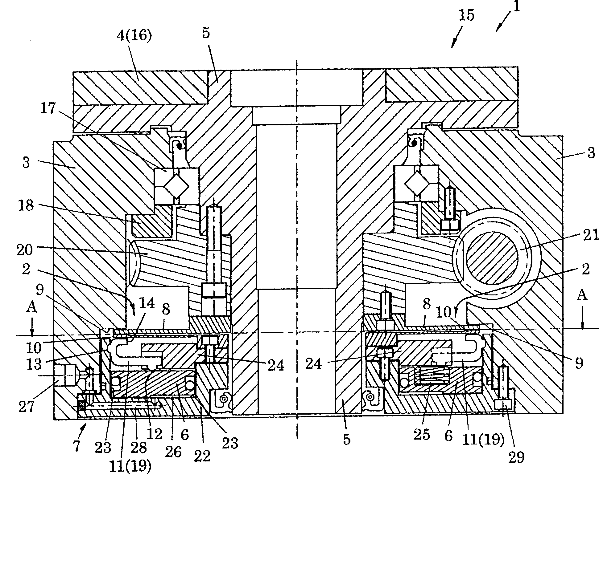
[0027] figure 1 A rotary table device 15 as an example of the rotary indexing device 1 for machine tools used in the present invention is shown. The rotary table device 15 is a device in which a circular table 16 as a member 4 to be rotationally driven is rotatably attached to a housing 3 as a base. Also known as indexing table, rotary table.

[0028] Next, the rotary table device 15 will be described in more detail. The circular table 16 is fixed to one end of a rotating shaft 5 rotatably provided in the casing 3 , and the rotating shaft 5 is rotatably supported by a bearing 17 fixed to the casing 3 by a bearing sleeve 18 .

[0029] In addition, the rotary table device 15 has as the driving mechanism of the round table 16: a worm wheel 20 fixed on the rotating shaft 5, a worm 21 rotatably supported on the housing 3 and meshed wi...

Example Embodiment

[0041] Example 2

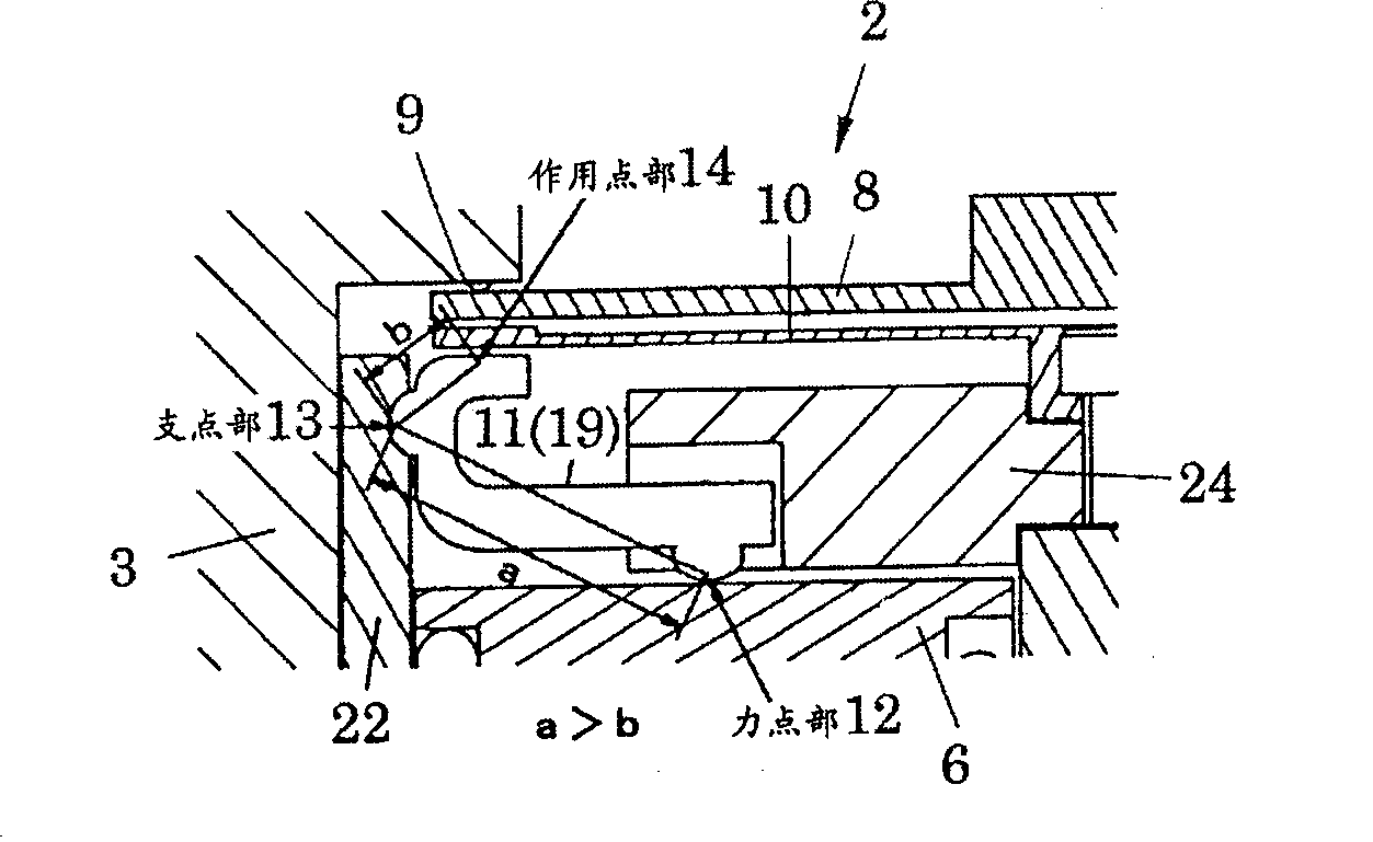
[0042] Figure 4 and Figure 5 In the rotary table device 15 similar to that of the first embodiment, an example in which a member of another shape is used for the lever member 11 (clamp lever 19) is shown. In the clamping mechanism of the first embodiment, the fulcrum portion 13 is formed between the action point portion 14 and the force point portion 12 , but in this embodiment, the action point portion 14 is formed between the fulcrum portion 13 and the force point portion 12 . In this way, as long as the distance a from the force point 12 to the fulcrum 13 is longer than the distance b from the fulcrum 13 to the action point 14, the lever member 11 can be designed in various shapes.

Example Embodiment

[0043] Example 3

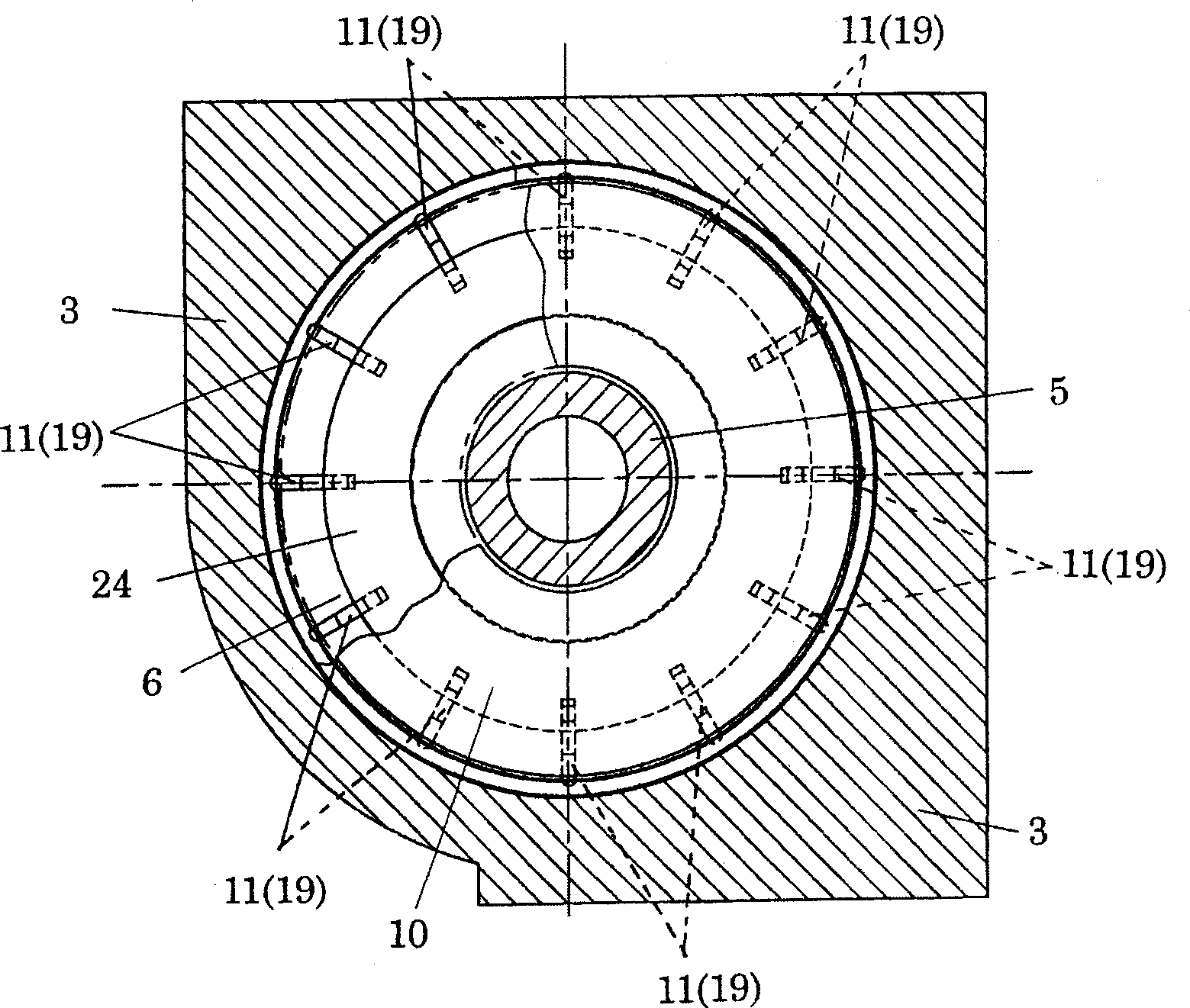
[0044] Image 6 This is an example in which the clamp member 10 (clamp ring) is fixed to the cover member 22 on the outer peripheral side in the same rotary table device 15 as in the first embodiment. In addition, in this embodiment, among the parts constituting the clamping device 2, parts other than the clamping disk 8 are unitized, but if the unitized structure of the clamping device 2 is not considered, The outer peripheral surface of the piston member 6 may be guided by the housing 3 to displace it in the axial direction, or the clip member 10 may be directly fixed to the housing 3 by being fixed to the cover member 22 as shown in the illustrated example.


PUM


Abstract

The present invention relates to a clamping device of a rotation indexing device used by a machine tool. The invention provides a clamping mechanism which can endure high-load procession and generates enough clamping force in the clamping device of a rotation indexing device used by a machine tool. The clamping device (2) is provided with a clamping mechanism which is set with a mode of extending along a radius direction of rotation axis (5) and is composed of more than three lever components (11) between a clamping disc (8) and a piston component (6). The pulling force of the piston component (6) is increased through a lever principle and is acted on the clamping disc (8).

Description

technical field [0001] The invention relates to a clamping device for a rotary indexing device for a machine tool. Background technique [0002] Patent Document 1 - Japanese Unexamined Patent Publication No. 10-220425 discloses a prior art rotary table device as a rotary indexing device having a clamping device, which is a premise of the present invention. The clamping device of the rotary table device is a so-called disc-type clamping device, which uses hydraulic pressure to make the displacement piston squeeze the piston's extrusion surface against the clamping disc. The cooperating action clamping of the tight face is fixed on the rotating shaft of the rotary table to clamp the disc to maintain the indexing position of the rotary table. [0003] For this type of disc clamping device, the piston part is displaced to the side of the clamping disc by supplying the working fluid (pressure oil, etc.) It is a common structure to act a pushing force on the clamp disk, but in t...

Claims


Application Information

Patent Timeline
IPC IPC(8): B23Q16/08B23Q16/10
CPCB23Q2220/004B23Q16/105B23Q16/02B23Q16/04
Inventor 辰田好教
Owner TSUDAKOMA KOGYO KK
Why Eureka
Try Eureka