Method for monitoring sleeve circumferential strain by using optical fibre grating sensor

A fiber grating and circumferential strain technology, applied in the direction of optical devices, measurements, instruments, etc., can solve problems such as corrosion, inaccurate casing circumferential strain signals, and susceptibility to downhole electromagnetic interference, and achieve the effect of ensuring stability

Inactive Publication Date: 2009-04-01
DAQING OILFIELD CO LTD
View PDF0 Cites 43 Cited by
  • Summary
  • Abstract
  • Description
  • Claims
  • Application Information

AI Technical Summary

Problems solved by technology

[0003] In order to solve the problem of inaccurate measured casing circumferential strain signals due to the use of resistance strain gauges in the existing technology of monitoring casing circumferential deformation, which is easily affected by downhole electromagnetic interference and corrosion, the present invention provides an optical fiber The method of grating sensor monitoring the circumferential strain of the casing, the application of this method, has the characteristics of not being disturbed by downhole electromagnetic interference, and the fiber grating sensor group used has been specially modified, which is very corrosion-resistant and is very suitable for the harsh environment of the downhole use

Method used


Image

  • Method for monitoring sleeve circumferential strain by using optical fibre grating sensor
  • Method for monitoring sleeve circumferential strain by using optical fibre grating sensor
  • Method for monitoring sleeve circumferential strain by using optical fibre grating sensor

Examples


Embodiment Construction

[0030] The present invention will be further described below in conjunction with accompanying drawing:

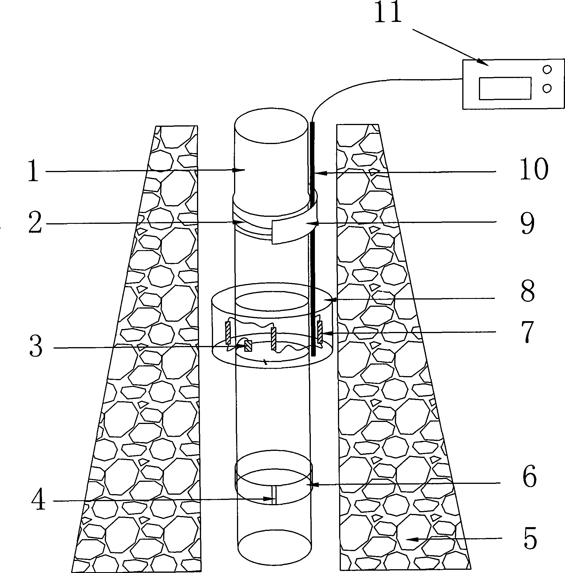
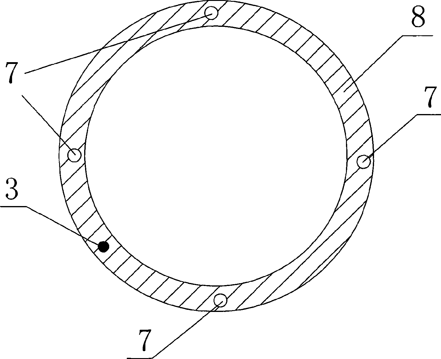
[0031] The method described in the present invention is to apply the optical fiber grating sensor principle, and arrange the optical fiber grating sensor along the circumferential direction of the casing outside the surface of the preset casing in the section where the casing loss occurs frequently. Wherein a plurality of bare fiber grating sensors are evenly distributed around the casing, and adjacent interval sections form a certain angle. Arrange fiber optic temperature compensation sensors at corresponding distances from this group of sensors. The fiber grating sensor is used to monitor the micro-deformation of the casing and its stress within a certain range from the sensor, and the temperature compensation sensor is used as the temperature compensation of the strain sensor and downhole temperature monitoring. The sensor transmits the underground signal to the ground ...


PUM


Abstract

The invention relates to a method for monitoring the circumferential strain of a casing by applying optical-fiber grating sensors, which mainly solves the problem that an electric-resistance strain gauge adopted of the current technology for monitoring the circumferential deformation of the casing is easy to be affected by electromagnetism in a well and corrosion, thus causing a measured circumferential strain signal of the casing to be inaccurate. The method is characterized in that: the optical-fiber grating sensors are arranged outside the casing along the circumferential direction of the casing, wherein, a plurality of optical-fiber grating sensors are evenly arranged around the casing; sections of adjacent intervals form a certain angle; an optical-fiber temperature compensating sensor is arranged in a position at a corresponding distance away from the group of sensors; the optical-fiber grating sensors are applied to monitoring the circumferential deformation and stress status of the casing within certain ranges; meanwhile, the temperature compensating sensor is applied to serving the temperature compensation and temperature monitoring in the well of the strain sensor; the sensors transmit underground signals to the ground by a transmission optical cable; and the signals can be transformed into the circumferential strain information of the casing after a demodulation instrument obtains the signals and carries out secondary treatment. The method is characterized by not being affected by the underground electromagnetism.

Description

Technical field: [0001] The invention relates to a method for monitoring the circumferential strain of the casing in the field of oil field casing damage research, in particular to a method for monitoring the circumferential strain of the casing based on the fiber grating sensor and using the fiber grating sensor. Background technique: [0002] At present, in the research field of casing damage of oil and water wells in the oil field, the method of monitoring the circumferential deformation of the casing outside the pipe is: laying resistance strain gauges outside the casing surface, and then transmitting the strain electrical signals generated by the resistance strain gauges to the ground. The biggest problem with this method is that the resistance strain gauge is easily affected by downhole electromagnetic interference and corrosion, resulting in inaccurate measured casing circumferential strain signals. Invention content: [0003] In order to solve the problem of inacc...

Claims


Application Information

Patent Timeline
Patent Type & Authority Applications(China)
IPC IPC(8): E21B47/00G01B11/16
Inventor 刘合王中国姚洪田林发枝王清平孙晓明龙云飞
Owner DAQING OILFIELD CO LTD
Why Eureka
Try Eureka