Stamping apparatus

A pressure chamber and chamber technology, applied in optics, opto-mechanical equipment, instruments, etc., can solve problems such as difficult separation, soft mold deformation or damage, and achieve the effects of easy separation, reduced size, and reduced space

Inactive Publication Date: 2009-04-01
WEIHAI DMS OPTICAL ELECTROMECHANICAL CO LTD
View PDF0 Cites 5 Cited by
  • Summary
  • Abstract
  • Description
  • Claims
  • Application Information

AI Technical Summary

Problems solved by technology

[0013] Moreover, when the soft mold is separated from the substrate from the contact state, it is sometimes difficult to separate it because the resin layer on th

Method used


Image

  • Stamping apparatus
  • Stamping apparatus
  • Stamping apparatus

Examples


Embodiment Construction

[0038] Hereinafter, preferred embodiments of the present invention will be described in detail in conjunction with the accompanying drawings.

[0039] The following descriptions are within the scope of implementation by those skilled in the art.

[0040] Therefore, the embodiments of the present invention may have various modifications, and the protection scope thereof is not limited to the following embodiments.

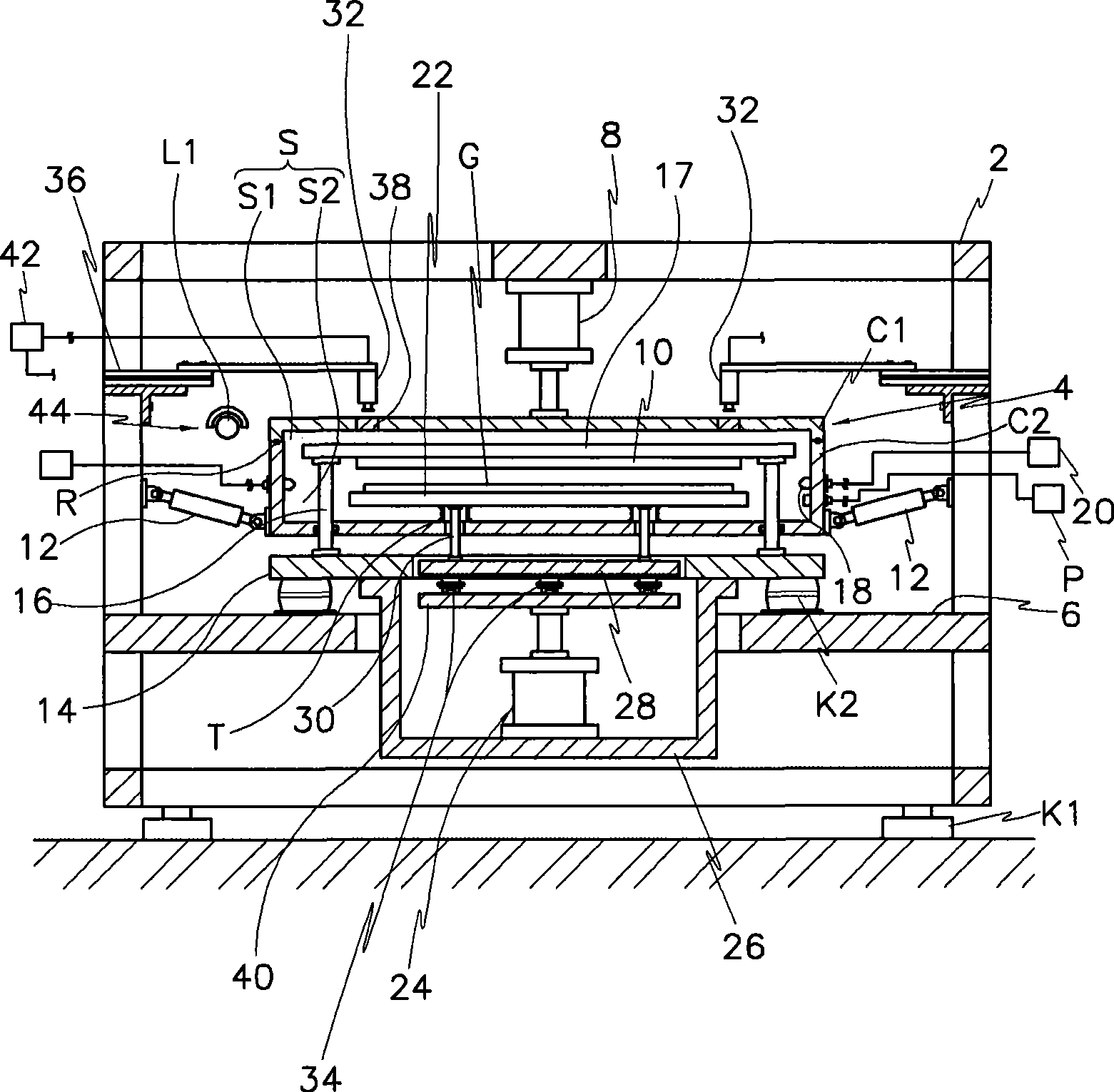
[0041] figure 1 It is a schematic diagram of the overall structure of an embodiment of an imprinting device for forming an etching region on a substrate according to the present invention, wherein reference numeral 2 denotes a frame.

[0042] The frame 2 is a rectangular frame formed by welding or screwing a plurality of metal pipes (or metal strips) by a conventional method, which is preferably supported on the ground by a backing plate K1 such as a rubber plate, so as to absorb the floor shock force.

[0043] Furthermore, a cavity 4 is provided on the inner sid...


PUM


Abstract

The present invention discloses an impression device which can form an etching area and a non-etching area on a substrate used by flat panel display element with a simple mode. The device comprises the following components: a frame; a chamber which is provided with a first chamber casing and a second chamber casing that are set one an upper position and a lower position on the frame and form an openable closing space through combining operation or separation operation; a soft mould which is provided with a pattern surface that is used for differentiating the etching area and non-etching area and is positioned in the closed space of chamber; an objective table which is provided with a loading surface that is used for loading the substrate and moves up-and-down relatively to the soft mould in the closed space of chamber; and a hardening mechanism which moves from one side to the other side of objective table and simultaneously irradiates ultraviolet.

Description

technical field [0001] The present invention relates to an imprinting device that can distinguish and form patterns of etching regions and non-etching regions on a flat panel display substrate in a simple manner, and in particular relates to an imprinting device that can further improve work efficiency when processing large-area substrates, and through uniform pressure to imprint the entire surface of the substrate, thereby providing an imprint device with improved pattern quality. Background technique [0002] In the manufacture of flat panel displays, in order to form etched regions and non-etched regions on the substrate, an exposure method based on a photosensitive liquid or an imprint method based on a soft mold is generally used. [0003] The imprinting device used in the imprinting method includes: a cavity shell with a sealed space, which can be switched between atmospheric pressure and vacuum pressure environment; the stage is arranged inside the cavity shell for A...

Claims


Application Information

Patent Timeline
IPC IPC(8): G03F7/00
CPCH01L21/6715H01L21/68778
Inventor 朴春成吴相泽申泰炅李真香郑昌镐李宰一
Owner WEIHAI DMS OPTICAL ELECTROMECHANICAL CO LTD
Why Eureka
Try Eureka