Three-dimensional reconstruction method based on fringe photograph collection of same scene

A three-dimensional reconstruction and scene technology, which is applied in 2D image generation, image data processing, instruments, etc., can solve problems such as high time overhead, unreliable basic matrix, and return time overhead, and achieves improved stability and accuracy. Reliable camera pose estimation, the effect of overcoming accumulated errors

Inactive Publication Date: 2009-04-01
BEIHANG UNIV
View PDF0 Cites 30 Cited by
  • Summary
  • Abstract
  • Description
  • Claims
  • Application Information

AI Technical Summary

Problems solved by technology

However, there are defects in this method: 1) Assuming that the matching error rate is very high, the RANSAC algorithm eliminates few false matches, and the calculated fundamental matrix is ​​unreliable; 2) The best matching pair is used as the initial camera pair for SfM, regardless of the degradation It is very easy to lead to ill-posed estimation; 3) The restored geometric information is sparse three-dimensional feature points, which is far from meeting the visual needs
This method fills the gap between the sparse method and the dense method, and increases the width of a well-matched baseline, but it is also not suitable for complex situations. Only when the internal parameters of the camera change small, the two views of the larger baseline ca

Method used


Image

  • Three-dimensional reconstruction method based on fringe photograph collection of same scene
  • Three-dimensional reconstruction method based on fringe photograph collection of same scene
  • Three-dimensional reconstruction method based on fringe photograph collection of same scene

Examples


Embodiment Construction

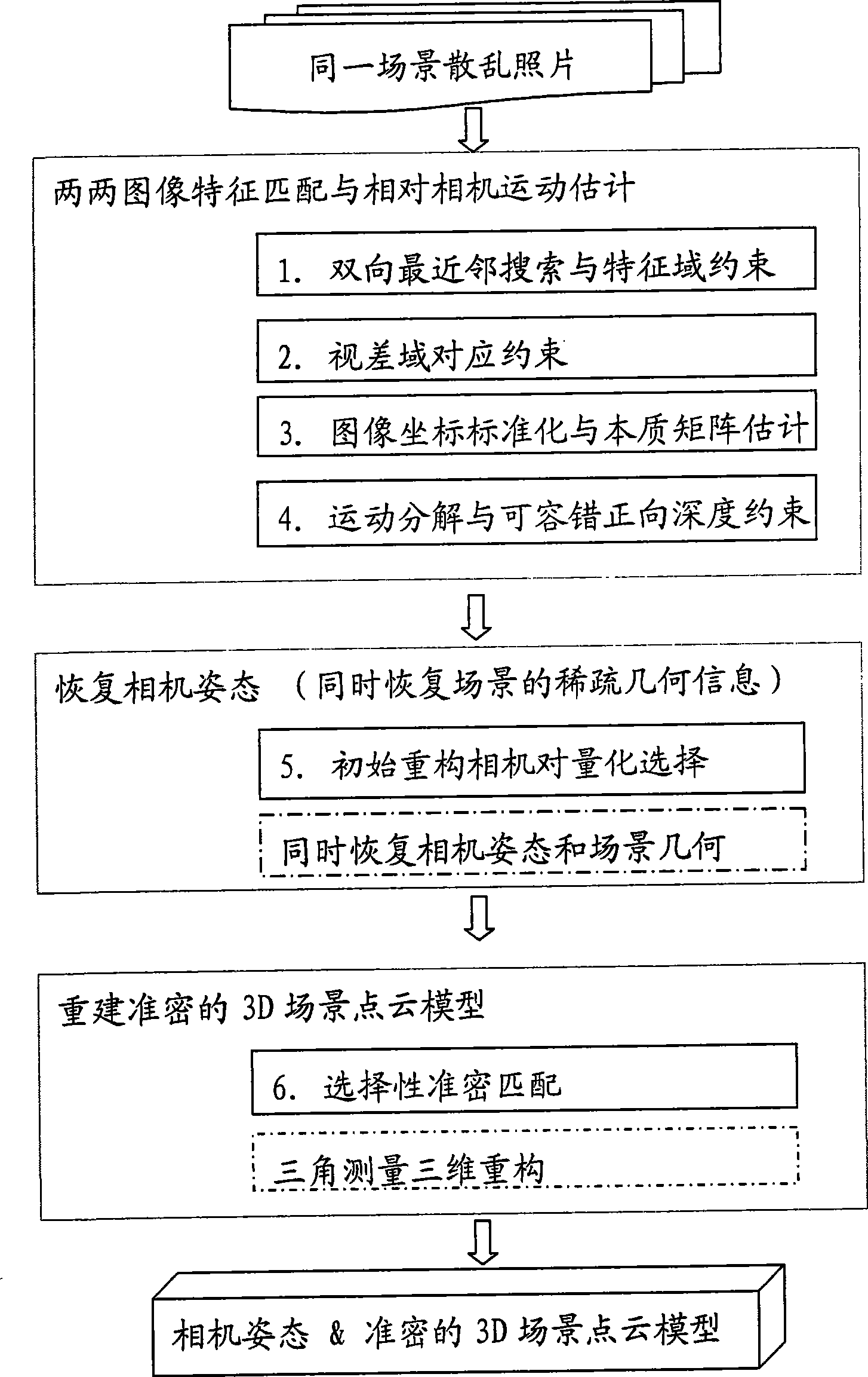
[0031] Such as figure 1 Shown, concrete steps of the present invention are as follows (the step in the dotted line frame is prior art):

[0032] 1. Perform bidirectional nearest neighbor search and feature domain constraints on each two images to obtain candidate correspondences.

[0033] The advantage of bidirectional nearest neighbor search and feature domain constraints is that when pairwise image features are matched, more potential matches are searched in the forward direction, and constraints are strengthened in the reverse direction, which can not only obtain more candidate correspondences, but also improve the accuracy rate. The method for:

[0034] For two images (I 1 , I 2 ), for each feature point p on I1 i , find it in I 2 Candidate corresponding points on , the steps are as follows:

[0035] In the first step, the user sets the forward and reverse feature domain constraint ratios as rt 1 , rt 2 ;

[0036] In the second step, in I 2 look for p i k = 5 ne...


PUM


Abstract

A 3D reconstruction method based on scattered photo sets of the same scene is divided into three stages: the first stage: every pairwsie image feature matching and relative camera motion are estimated; and the stage is divided into 4 steps: (1) every two images are subject to the bidirectional nearest neighbor search and feature domain constraint to obtain a candidate correspondence; (2) the candidate correspondence is subject to parallax domain correspondence constraint to obtain a hypothesis correspondence; (3) the image coordinates of the hypothesis correspondence are standardized to solve an essential matrix estimation meeting the hypothesis correspondence; (4) the essential matrix is decomposed to obtain four groups of possible solutions of the camera motion, and the final solution is determined by the fault-tolerant forward depth constraint; the second stage: the optimized initial reconstruction camera pair is selected according to the results of the first stage, the standard sparse reconstruction method is applied, and the camera pose and the sparse geometric information of the scene are restored; the third stage: selective accurate and dense matching is carried out based on the results of second stage, and an accurate and dense 3D scene point cloud model is reconstructed by the triangulation method. The method has the advantages of obtaining reliable camera pose and high-density scene geometric information, greatly shortening the reconstruction time, having relatively high reconstruction efficiency, and is applicable to processing the scattered photo set with large data size.

Description

technical field [0001] The invention belongs to the field of virtual reality technology and computer vision. Specifically, three-dimensional reconstruction is carried out by scattered photos of the same scene, including restoring the shooting position, direction and field of view of the camera, and a dense 3D scene point cloud model. It is mainly used for Three-dimensional organization of digital photo resources on PC or Internet, as well as image-based drawing and browsing, etc. Background technique [0002] In computer vision, the 3D reconstruction theory and algorithm of multi-view geometry have been developed more maturely in the past two decades, document 1—R. Hartley, and A. Zisserman, Multiple View Geometry in Computer Vision, Cambridge University Press, 2000. Derived and summarized relevant theories and algorithms comprehensively and deeply. For different situations where the camera has been calibrated or not, the method of recovering the unknown 3D scene structure ...

Claims


Application Information

Patent Timeline
IPC IPC(8): G06T11/00
Inventor 齐越沈旭昆何爽
Owner BEIHANG UNIV
Why Eureka
Try Eureka