
Generator for vehicle

A technology for generators and vehicles, which is applied in the direction of machines/engines, synchronous machines, electromechanical devices, etc. It can solve problems such as difficulty in obtaining large inclination angles, large spaces, and easy enlargement of generator covers, and achieve the effect of improving versatility

Inactive Publication Date: 2009-04-01
HONDA MOTOR CO LTD
View PDF2 Cites 16 Cited by
  • Summary
  • Abstract
  • Description
  • Claims
  • Application Information

AI Technical Summary

Problems solved by technology

[0005] In the vehicle generators disclosed in Patent Documents 1 and 2, a relatively large space is required between the outer periphery of the outer rotor directly connected to the crankshaft and the inner peripheral surface of the generator cover, and therefore the generator cover tends to become larger.
Especially in motorcycles, the generator cover is often arranged to protrude from the side of the vehicle body. Therefore, if the generator cover is large, it is difficult to obtain a large inclination angle.

Method used


Image

  • Generator for vehicle
  • Generator for vehicle
  • Generator for vehicle

Examples


Embodiment Construction

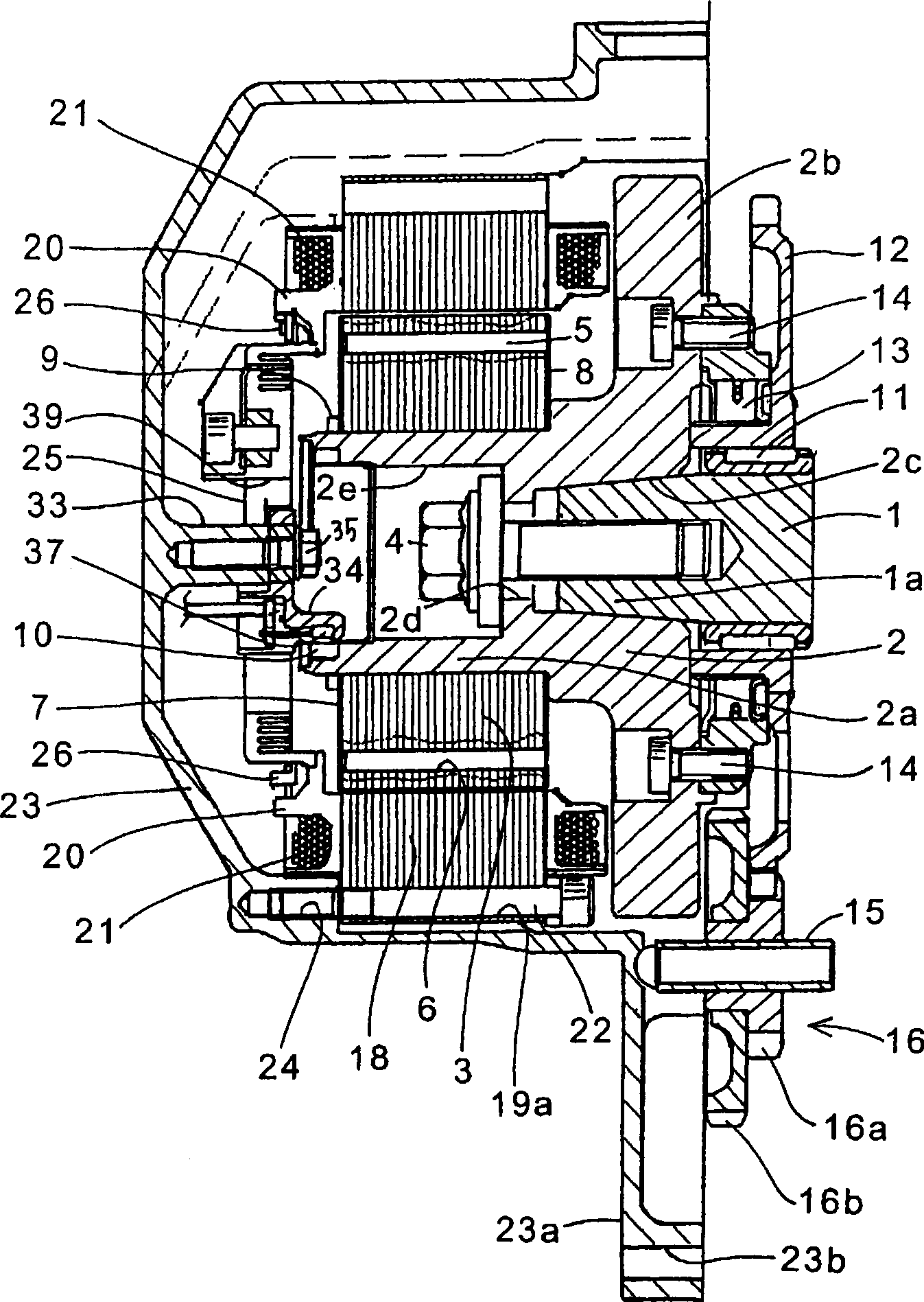
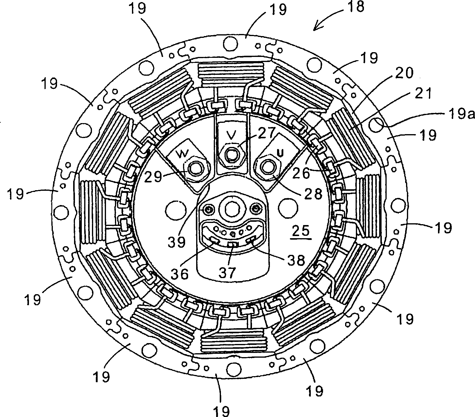
[0050] One embodiment of the present invention will be described below with reference to the drawings. figure 1 It is a cross-sectional view of a vehicle generator according to an embodiment of the present invention. figure 2 It is a front view of the vehicle generator with the generator cover removed, that is, a front view of the stator portion of the generator.

[0051] exist figure 1 Among them, for example, an outer peripheral surface of a front end portion 1 a of a crankshaft 1 mounted on an engine of a motorcycle has a tapered shape, and the front end portion 1 a is fitted into a center hole of a rotor hub 2 . The rotor hub 2 is composed of a cylindrical portion 2a in which the rotor core 3 is fitted on the outer periphery, and a flange 2b formed on one end side of the cylindrical portion 2a. The cylindrical portion 2a includes: a tapered inner peripheral surface 2c adapted to the tapered outer peripheral surface of the front end portion 1a of the crankshaft 1; a bolt...


PUM


Abstract

The invention provides a generator for vehicle that is miniaturized and uses space in a generator cover effectively. The generator for vehicle has a rotor boss (2) engaged with a crankshaft (1) with a rotor core (3) engaged with the outer circumference of the rotor boss. A stator core (18) is provided around the outer circumference of the rotor core (3) with a bus ring (25) opposed to one end surface of the rotor core (3). The outer circumference of the bus ring (25) is engaged with a plurality of insulating components (20) surrounding the teeth. A rotation angle detection sensor (37) of the rotor boss (2) is configured opposite to a sensor magnet (10) in front of the rotor boss (2). The stator core (18) has a split structure. Each stator core block (19) is fixed to a generator cover (23) by a bolt. The generator cover (23) is fixed to the outer surface of a crankcase. The rotor core (3) is formed with a plurality of holes (6) for respectively supporting a plurality of rotor magnets (5). The bus ring (25) includes a plurality of terminals (26) and grommets (27-29) connected through bus bars (25a) to the terminals.

Description

technical field [0001] The present invention relates to a vehicle generator, and more particularly to a vehicle generator capable of downsizing by effectively utilizing the space in a generator cover. Background technique [0002] As a generator for a vehicle driven by an engine, there is known a structure in which an external rotor with permanent magnets that doubles as a flywheel is attached to a crankshaft serving as an output shaft of the engine, and an internal stator having a winding is attached to the power generator. On the hood (JP-A-2002-112594 Gazette, JP-A-2001-286100 Gazette). [0003] Japanese Patent Document 1: Japanese Unexamined Patent Publication No. 2002-112594 [0004] Japanese Patent Document 2: Japanese Unexamined Patent Publication No. 2001-286100 [0005] In the vehicle generators disclosed in Patent Documents 1 and 2, a relatively large space is required between the outer periphery of the outer rotor directly connected to the crankshaft and the inn...

Claims


Application Information

Patent Timeline
Patent Type & Authority Applications(China)
IPC IPC(8): H02K21/12H02K21/02H02K3/18H02K11/00H02K1/27H02K7/10H02K7/18F02B63/04
CPCH02K3/522H02K19/365H02K11/0021H02K11/215H02K9/02
Inventor 小林直树柴田和己生井邦明塚本智宏青木宏二
Owner HONDA MOTOR CO LTD
Learn More