

Overcurrent protection circuit for photovoltaic DC-to-AC converter
An overcurrent protection circuit, photovoltaic inverter technology, applied in emergency protection circuit devices, photovoltaic power generation, electrical components and other directions, can solve the problems of overcurrent protection malfunction, poor linearity of sampling circuit, weak anti-interference ability, etc. Achieve the effect of suppressing the current growth, reliable protection function and good working reliability
Inactive Publication Date: 2010-12-01
INST OF ELECTRICAL ENG CHINESE ACAD OF SCI +1
View PDF0 Cites 0 Cited by
- Summary
- Abstract
- Description
- Claims
- Application Information
AI Technical Summary
Problems solved by technology
Solution 1 can detect the large current flowing through the circuit when the load side is short-circuited or overloaded, and apply specific protection measures to the power switch. Failure, the overcurrent protection circuit cannot achieve the purpose of protecting the circuit
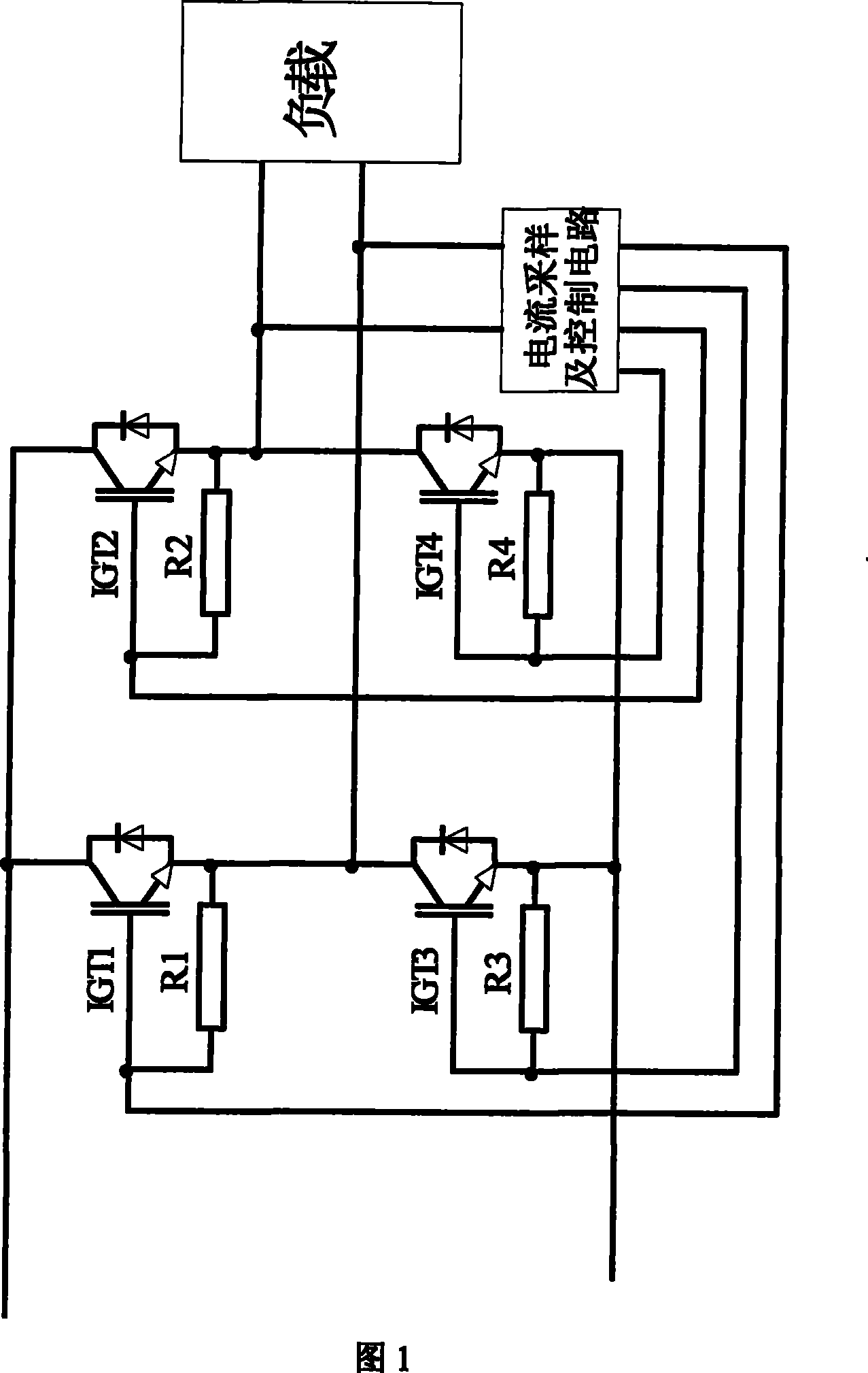
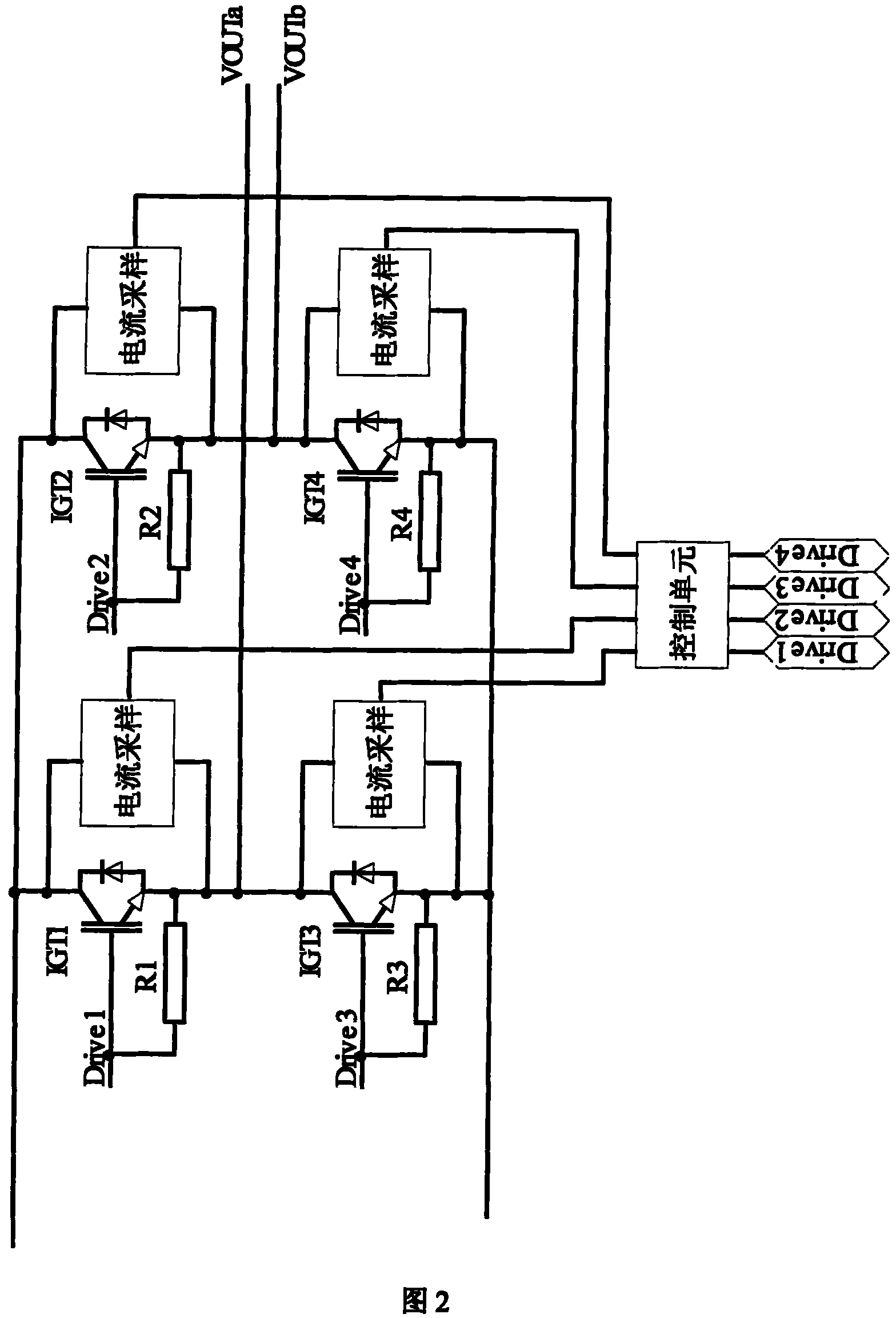
Scheme 2 uses a set of sampling circuits on each switch tube, which can still serve the purpose of circuit protection when the upper and lower bridge arms of the rectifier-inverter bridge are connected directly. The problem of scheme 2 is that the linearity of the sampling circuit is poor. The current sampling value changes nonlinearly, so it is difficult to determine the overcurrent point or overcurrent value of the current flowing through the power device, and the anti-interference ability is also weak
When the over-current point is set too low due to interference or inaccurate measurement, the over-current protection will malfunction, and on the contrary, the device will be burned due to over-current.
In addition, there is a common problem in scheme 1 and scheme 2, that is, the protection of power devices in these two schemes is finally realized by blocking the driving pulse, which leads to the engine power switch due to overcurrent. In the case of blocking effect, only blocking the driving pulse cannot effectively protect the power switch tube
Method used
View moreImage
Smart ImageViewing Examples

Examples
Embodiment Construction
Login to View More PUM
 Abstract
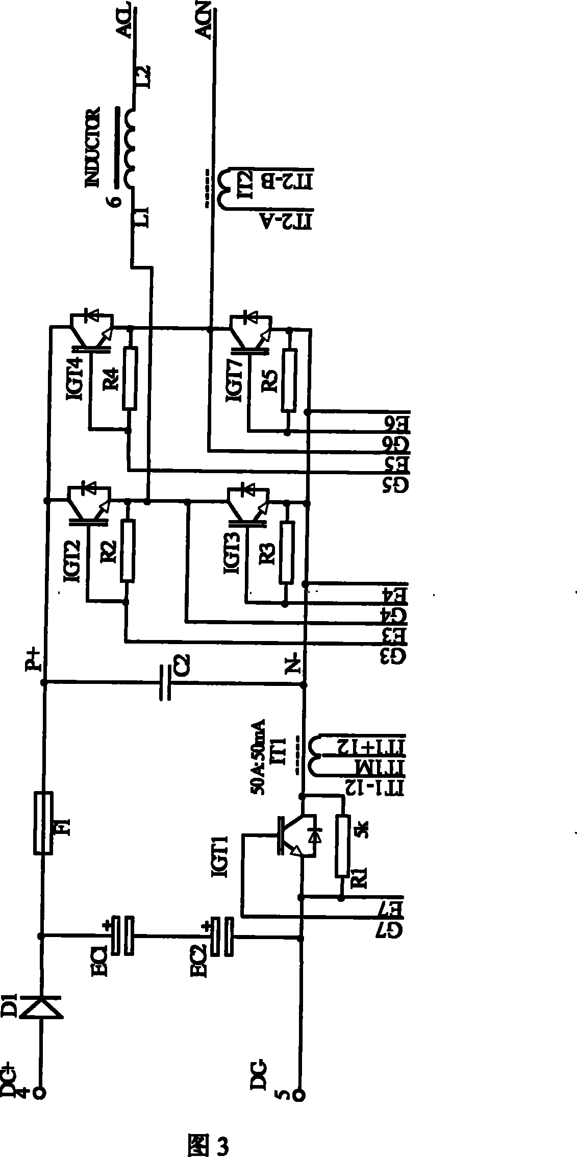
The invention relates to a current foldback circuit of photovoltaic inverters which comprises a main current foldback circuit, an overcurrent protection driving circuit and an overcurrent protection control circuit. The main current foldback circuit is connected with the overcurrent protection control circuit by the output terminals of IT1M, IT2-A and IT2-B; the overcurrent protection control circuit is connected with the overcurrent protection driving circuit by the terminals of IDRV+ and IDRV-; and the overcurrent protection driving circuit is connected with the main current foldback circuit by the terminals of IG and IE. The DC side current sensor IT1 in the main current foldback circuit samples the current in the DC busbar, the AC side current sensor IT2 samples the AC output current,the two sample values are output to the overcurrent protection control circuit which sends out the control signals to the overcurrent protection driving circuit by logistic judgment, the overcurrent protection driving circuit transforms the control signal to the signal for driving an overcurrent protection switching tube IGT1, so as to control on and off of the switching tube IGT1.
Description
Photovoltaic inverter overcurrent protection circuit technical field The invention relates to a photovoltaic inverter overcurrent protection circuit. Background technique In the field of traditional circuit technology, situations such as load short circuit and power switch tube straight-through often cause the power switch tube to flow through a large current, or cause other components in the circuit to flow through a large current. If it is not prevented and suppressed, the circuit will fail. May burn out due to high current flow. An overcurrent protection circuit is a circuit that protects the entire circuit from damage when a large current flows through the circuit. In general applications, the main object of overcurrent protection is the power switch tube, which prevents the current flowing through the power switch tube from exceeding the design limit when the circuit is abnormal. Traditional overcurrent protection schemes mainly include: Solution 1 is to perform ...
Claims
Login to View More Application Information
Patent Timeline
 Patent Type & AuthorityPatents(China)
IPC IPC(8): H02M1/32H02H7/122
CPCY02E10/56
Inventor刘四洋许洪华彭燕昌徐正国
OwnerINST OF ELECTRICAL ENG CHINESE ACAD OF SCI