Method for manufacturing wiping rod

A manufacturing method and a technology for wiping sticks, which are applied in the directions of cleaning methods using tools, cleaning methods and utensils, chemical instruments and methods, etc., can solve the problems of poor hot-melt effect at the adhesion point, easy to fall off, and unable to implement the action, etc. Improve the efficiency of wiping work, combine closely, and broaden the scope of use

Inactive Publication Date: 2009-04-08
刘颖姝
View PDF0 Cites 5 Cited by
  • Summary
  • Abstract
  • Description
  • Claims
  • Application Information

AI Technical Summary

Problems solved by technology

But this kind method tends to produce sliding situation between the front end (31) of the headgear (2) and the rod (3) when wiping because there is no comprehensive bonding between the headgear (2) and the rod (3), so that The action cannot be implemented; and the hot melt effect at the adhesion point (34) is not good, and it is easy to fall off, causing inconvenience in use

Method used


Image

  • Method for manufacturing wiping rod
  • Method for manufacturing wiping rod
  • Method for manufacturing wiping rod

Examples


Embodiment 1

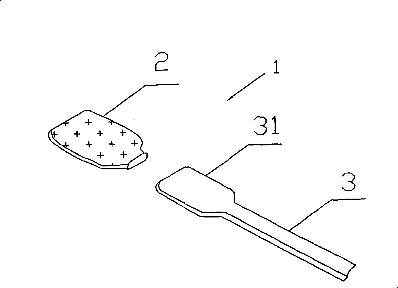
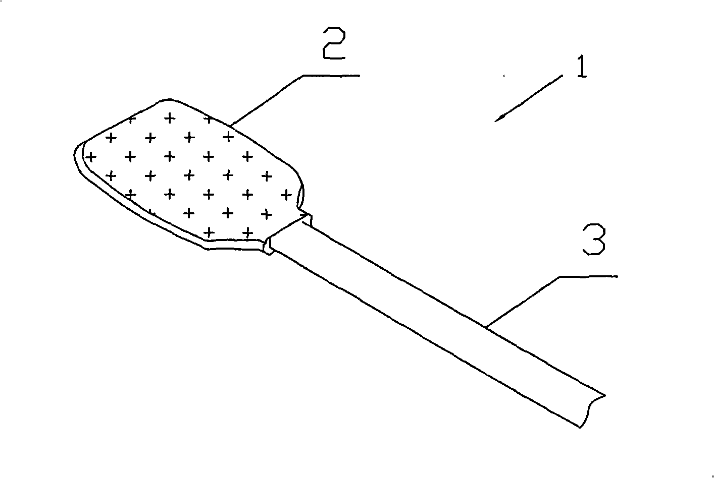
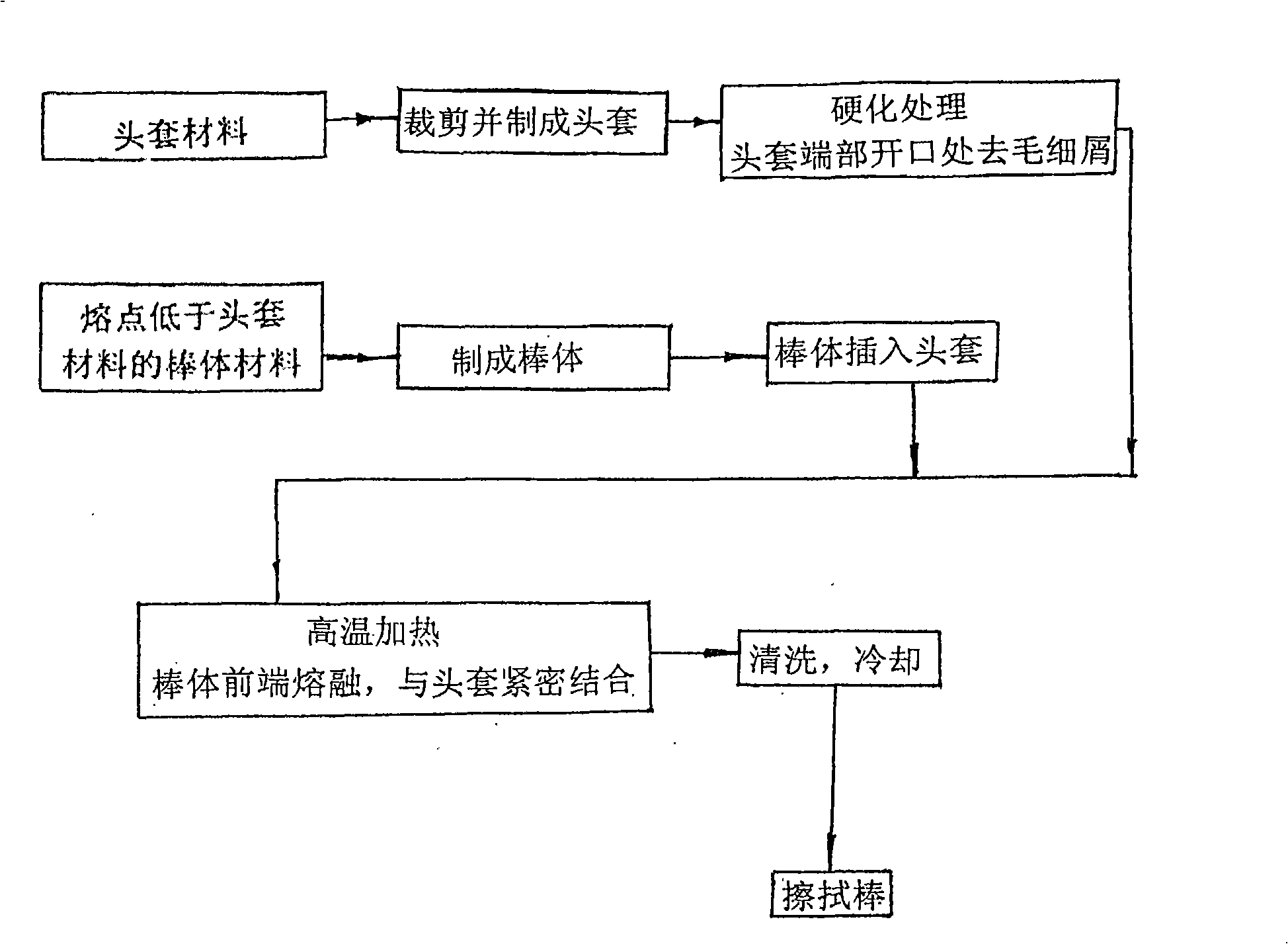
[0025] Embodiment 1 A kind of manufacturing method of wiping stick, such as figure 1 and figure 2 As shown, nylon cloth is used as the material of the head cover 2 , and polyethylene plastic, which has a melting point lower than that of the nylon cloth, is used as the material of the rod body 3 . The nylon cloth is cut and processed into the head cover 2 , and the material of the rod body 3 is made into the rod body 3 whose front end 31 is the same size as the head cover 2 . another example image 3 , Figure 4 and Figure 5 As shown, hardening heat treatment is performed on the port part of the head cover 2 (that is, the insertion part of the rod body 3). During the hardening process, the position heated by the hardening heat processor 41 is 2 mm away from the port of the head cover 2; the heating temperature is 250°C; the pressure is <0.3Mpa; the contact time is 1.5 seconds. The port part of the hardened headgear 2 has been converted from nylon cloth to nylon sheet, a...

Embodiment 2

[0026] In Example 2, basically the same procedure as in Example 1 was carried out. like figure 1 and figure 2 As shown, nylon cloth is used as the material of the head cover 2 , and polyethylene plastic, which has a melting point lower than that of the nylon cloth, is used as the material of the rod body 3 . The nylon cloth is cut and processed into the head cover 2 , and the material of the rod body 3 is made into the rod body 3 whose front end 31 is the same size as the head cover 2 . another example image 3 , Figure 4 and Image 6 As shown, hardening heat treatment is performed on the port part of the head cover 2 (that is, the insertion part of the rod body 3). During the hardening process, the position heated by the hardening heat processor 41 is 2 mm away from the port of the head cover 2; the heating temperature is 250°C; the pressure is <0.3Mpa; the contact time is 1.5 seconds. The port part of the hardened headgear 2 has been converted from nylon cloth to nyl...

Embodiment 3

[0027] In Example 3, basically the same procedure as in Example 1 was carried out. The sponge is used as the material of the head cover 2 , and the material with a melting point lower than that of the sponge, polyethylene plastic, is used as the material of the rod body 3 . The sponge is cut and processed into the head cover 2 , and the material of the rod body 3 is made into the rod body 3 whose front end 31 is the same size as the head cover 2 . another example image 3 , Figure 4 and Figure 5As shown, the port portion of the headgear 2 (ie, the insertion portion of the rod body 3 ) is subjected to a hardening heat treatment. During the hardening process, the hardening heat processor 41 is not in contact with the sponge head cover 2, but is in the form of radiant heating. The position heated by the hardening heat processor 41 is 4 mm away from the port of the headgear 2; the heating temperature is 200° C.; the pressure is <0.4 Mpa; the contact time is 2 seconds. The o...


PUM


Abstract

The invention discloses a method for manufacturing a wiping rod, which relates to a method for combining a sleeve and a rod body of the wiping rod, and a method for removing rough edges of the sleeve, wherein a sleeve material is cut and spliced into the sleeve; a rod body material is prepared into the rod body the dimension of the front end of which is the same as that of the sleeve, and the melting point of the rod body material is lower than that of the sleeve material; a port position of the sleeve, namely the rod body, is inserted into a sleeve position and placed into a hardening heat treater for hardening treatment; the front end of the rod body is placed into the sleeve, and the sleeve provided with the front end of the rod body is placed into a heater for overall or local high-temperature heat treatment; and after the melting point of the rod body material is achieved and the front end of the rod body is fused, the wiping rod is taken out, cleaned and cooled. When the wiping rod is used, people do not need to worry about that the clean surface can be polluted by wool fleece. The sleeve of the wiping rod and the front end of the rod body undergo high-temperature heat treatment and are tightly combined with each other, so that the wiping work efficiency is improved; and the wiping rod can resist various chemical detergents, so that the use range of the wiping rod is widened.

Description

technical field [0001] The invention relates to a manufacturing method of a wiping stick, in particular to a method for combining a head cover and a stick body in a wiping stick and a method for eliminating the burrs of the head cover. Background technique [0002] Before the present invention is proposed, a general wiping stick includes a head cover and a stick body. There are two methods for bonding between the head cover and the rod body, one method is to apply an adhesive (such as Image 6 shown), apply the adhesive (33) to the front end (31) of the rod body (3) and insert it into the head cover (2), after the adhesive is dried, the head cover (2) will be connected to the rod body (3). ) implements a good combination. However, this method uses a volatile chemical solvent, which will pollute the environment of the workplace; and the adhesive (33) used in the wiping operation when the wiping stick is stained with chemical cleaning agent or alcohol will be damaged by the c...

Claims


Application Information

Patent Timeline
Patent Type & Authority Applications(China)
IPC IPC(8): B29D31/00B29C65/02B29C35/02B08B1/00B29K67/00B29K77/00B29D99/00
Inventor 刘颖姝
Owner 刘颖姝
Why Eureka
Try Eureka