Well bottom booster pump and its supercharging method
A booster pump and booster cylinder technology, applied in drilling equipment and methods, drilling equipment, earthwork drilling, etc., can solve the problems of fast moving parts, short service life, insufficient impact force, etc., to reduce drilling costs , Improve the drilling speed and shorten the drilling cycle
Active Publication Date: 2009-04-08
ZHONGCHAO LIANHE ENERGY SCI & TECH BEIJING CO LTD
View PDF2 Cites 21 Cited by
- Summary
- Abstract
- Description
- Claims
- Application Information
AI Technical Summary
Problems solved by technology
[0004] Such as U.S. Patent US 005787998A, it adopts a conventional single-cylinder double-acting supercharging scheme in which the power cylinder is arranged in the middle of two booster cylinders, and a slide valve with a conventional structure installed side by side is used as a pilot valve, and two poppet valves are used as a reversing main valve. Composed of reversing valves to achieve reversing, the structure of this booster pump is relatively complex, and almost 100% of the flow of the mud pump is used for boosting, its flow path is narrow, the flow rate is too high, the erosion is serious, and the speed of the moving parts is too fast , heavy impact, frequent mechanical breakage, and short service life. These problems cannot be solved. In addition, this booster pump can only use the power cylinder to discharge the mud to complete the bottom well purification. Since the pressure drop of the large nozzle is only about 3.15MPa, so Insufficient impact force affects the purification of the bottom of the well and weakens the function of hydraulic rock breaking
[0005] Another example is the "hydraulic automatic booster pump" published by the Chinese patent CN 02204123.0. In this scheme, most of the mud from the mud pump is purified at the bottom of the well through a large nozzle, and a small part of the mud enters the parallel circuit of the power cylinder through the reversing valve. Its advantages There are many, but there are many structural defects. For example, the pilot valve, the key component that affects the reliability of the booster pump, is a conventional slide valve structure. It is difficult to guarantee the service life of the sealing pair completely by wear-resistant and corrosion-resistant materials, and more importantly, since there is always mud passing between the sealing pairs, the problem of sand jamming cannot be avoided
Method used
View moreImage
Smart ImageViewing Examples
Examples
Embodiment Construction
[0058] The present invention will be described in further detail below in conjunction with the accompanying drawings.
Login to View More PUM
 Abstract
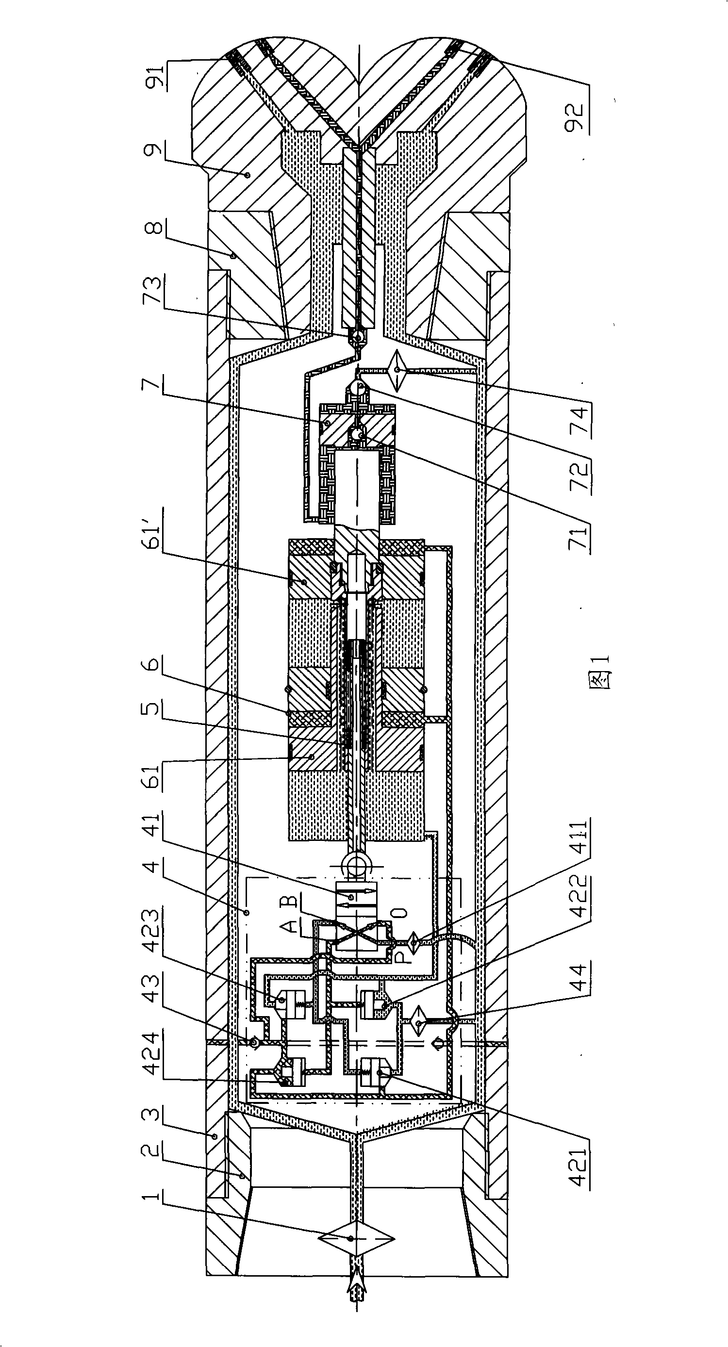
The invention discloses a bottom hole pressure pump and a pressurizing method thereof, wherein, the pressure pump mainly comprises a filter screen assembly, an upper end connector, a shell, a lower end fastening and an assorted double-channel drill bit. A change valve, a reversing control device, a power cylinder and a pressure cylinder are arranged in the shell sequentially, the lower end of the filter screen assembly is connected with the upper end connector by threads, the lower end of the upper end connector is connected with the shell by threads and sealed, the lower end fastening is connected with the shell by threads and sealed, and the left end of the lower end fastening props against the right end of the pressure cylinder, and presses and connects the change valve, the power cylinder and the pressure cylinder in the shell with a locking part arranged in the upper end connector. The invention can drastically improve the drilling speed, reduce the drilling cost and shorten the drilling period, and has relatively simple structure, short total length, low movement velocity, long service life, low manufacturing cost and high performance-price ratio.
Description
technical field [0001] The invention relates to oil drilling equipment, in particular to a well bottom booster pump capable of increasing the drilling speed in medium-hard rock formations and a booster method thereof. Background technique [0002] At present, in the field of oil drilling, the pumped mud output by the ground mud pump is used as the power of the booster pump, pressurized at the bottom of the well and cooperated with the dual-channel drill bit to realize the combined rock breaking of water and machinery, thereby greatly increasing the drilling speed and shortening the drilling time. It is an ideal technical measure to shorten the drilling cycle and reduce the drilling cost. [0003] However, under the condition that the bottom hole booster pump satisfies various drilling parameters, how to make the bottom hole booster pump reach the required value for industrial applications and keep the service life of the drill bit as close as possible has become a key factor...
Claims
Login to View More Application Information
Patent Timeline
 Patent Type & Authority Applications(China)
IPC IPC(8): E21B7/00E21B21/00E21B21/08F15B3/00
Inventor 李洪敏李蓉穆晓乐
Owner ZHONGCHAO LIANHE ENERGY SCI & TECH BEIJING CO LTD
Features
- R&D
- Intellectual Property
- Life Sciences
- Materials
- Tech Scout
- Unparalleled Data Quality
- Higher Quality Content
- 60% Fewer Hallucinations
Learn More Browse by: Latest US Patents, China's latest patents, Technical Efficacy Thesaurus, Application Domain, Technology Topic, Popular Technical Reports.
© 2025 PatSnap. All rights reserved.Legal|Privacy policy|Modern Slavery Act Transparency Statement|Sitemap|About US| Contact US: help@patsnap.com


