
Ultrasound phase-control emission fine delay control method based on digital wave-shape phase difference

A technology of digital waveform and phase difference, applied in the field of transmission delay of ultrasonic phased array, can solve the problems of insufficient delay quantization error, high computational load and memory support, etc., to suppress side lobes and improve delay resolution , the effect of improving the horizontal and vertical resolution

Inactive Publication Date: 2009-04-08
SOLID BEIJING TECH
View PDF0 Cites 11 Cited by
  • Summary
  • Abstract
  • Description
  • Claims
  • Application Information

AI Technical Summary

Problems solved by technology

Another method is to interpolate the sampled data in the time domain to obtain an N-fold dense output sequence to reduce the quantization delay. This requires a high amount of computation and memory support, and the delay quantization error is still not small enough.

Method used


Image

  • Ultrasound phase-control emission fine delay control method based on digital wave-shape phase difference

Examples


Embodiment Construction

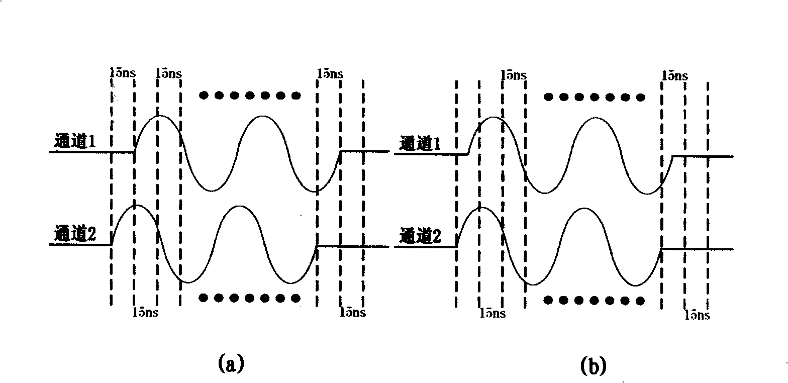
[0012] like figure 1 As shown in (b), the two channels store sine wave data with the same frequency but different phases. The D / A clocks are both 66MHz, and the launch delay values ​​are the same, that is, the data in the respective waveform SRAMs are read at the same time for D / A conversion. However, at the same time, the data read from the respective waveform SRAMs are different, and have a certain digital phase difference. The resolution of this phase difference is determined by the length of the following digital sine table.

[0013] The above is an intuitive description of the idea of ​​digital waveform phase difference from the perspective of graphics, and the following is a mathematical expression. During phased transmission, the phases of the mth and nth array elements at a certain moment can be expressed as:

[0014] φ m = ω 0 t m +θ m (1)

[0015] φ n = ω 0 t n +θ n (2)

[0016] ω 0 is the a...


PUM


Abstract

The key point of the ultrasonic phased array technique is the control of phase difference (time delay); all multi-phased control effects are based on phased time delay such as dynamic focusing and deflection of acoustic beams, forming of digital acoustic beams and the like, which depend on the realization of phased time delay; the precision of the phased time delay directly affects the whole performance of an ultrasonic phased system; the invention provides a novel method used for phase fine regulation; the method sufficiently utilizes the advantage of waveform motivation type, and adopts the method of digital waveform phase difference to realize fine delaying of phased emission, thus improving the phased emission delaying resolution. The digital waveform phase difference is the phase difference of digital waveforms of the same frequency memorized in waveform SRAM of different passages; and the digital waveform data is changed into analog excitation signal after D / A conversion and the digital waveform phase difference is converted into the phase difference of the analog excitation signal.

Description

technical field [0001] The invention relates to an ultrasonic phased array technology, in particular to an ultrasonic phased array transmission delay technology. Background technique [0002] The key digital technology in the ultrasonic phased array system mainly refers to the space-time control of the beam, using advanced digital electronic technology and microcomputer technology to precisely control the phased beam in the transmitting / receiving state to obtain the best beam characteristics. These key digital technologies include phased delay, dynamic focus, dynamic aperture, dynamic apodization, coded emission, acoustic beam forming, etc. [0003] The ultrasonic phased array system uses array transducers, and by adjusting the phase delay of the transmitted / received signals of each array element, the curvature, pointing, aperture, etc. of the synthetic wave front can be controlled to achieve beam focusing, deflection, beam forming, etc. Phase control effect, forming a clea...

Claims


Application Information

Patent Timeline
IPC IPC(8): G01N29/00G01N29/32G01N29/04G01B17/00G03B42/06A61B8/00
Inventor 彭春香勇彭波王敏
Owner SOLID BEIJING TECH
Learn More