Precision digital delay synchronization method based on phase compensation

A digital delay and phase compensation technology, applied in pulse processing, electrical components, pulse technology, etc., can solve the problems of delay precision operating frequency limitation, low integration, large trigger jitter, etc., to improve the delay resolution , The circuit is simple and reliable, and the effect of reducing the trigger error

Inactive Publication Date: 2018-09-28
INST OF FLUID PHYSICS CHINA ACAD OF ENG PHYSICS
View PDF6 Cites 21 Cited by
  • Summary
  • Abstract
  • Description
  • Claims
  • Application Information

AI Technical Summary

Problems solved by technology

The key of this method is to charge the capacitor on the rising edge of the external trigger and the phase of the clock to achieve time-to-amplitude conversion, and generate a delayed output signal through the back-end voltage comparator. Since the electric energy leakage will occur after the capacitor is charged, the jitter of the external trigger is relatively large. Large, generally less than 3ns can be achieved, while the circuit is complex and the integration level is not high
[0005] The invention patent of CN201010552082.2 "A Precise Digital Delay Synchronization Machine and Delay Method Based on Clock Phase-Splitting Technology" adopts the clock cycle for N times of phase-splitting, which can effectively reduce the trigger error of delay synchronization, and the external trigger jitter is less than 1ns, but the delay accuracy is limited by the operating frequency of the FPGA device, generally 2.5ns

Method used


Image

  • Precision digital delay synchronization method based on phase compensation
  • Precision digital delay synchronization method based on phase compensation
  • Precision digital delay synchronization method based on phase compensation

Examples


Embodiment 1

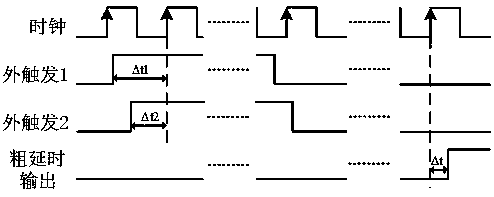
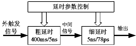
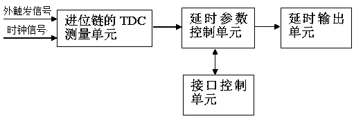
[0028] Such as figure 1 As shown, the circuit mainly includes a TDC based on a carry chain, a delay parameter control unit and a delay output unit. TDC is divided into two parts: time measurement and encoding circuit: time measurement is to introduce the external trigger signal to the special carry chain of FPGA, each carry chain delay unit is realized by the basic structure of FPGA, and each delay unit is followed by a register, which can Ensure that the current delay value is latched and output immediately when the clock edge arrives; and then through the back-end encoding circuit, the time interval between the external trigger signal and the rising edge of the next clock CLK can be obtained. The delay parameter control unit combines the phase relationship between the external trigger and the local clock and the preset delay parameters to calculate, and obtains the corresponding coarse count value and fine delay series. By setting the delay output unit, the delay output aft...


PUM


Abstract

The invention discloses a precision digital delay synchronization method based on phase compensation. The method comprises the following steps: measuring a phase relation between external triggering and a local clock by using a TDC based on a FPGA carry chain in one FPGA, performing computing by fusing the triggering relation between the external triggering and the local clock and the preset delayparameter by combining the coarse counting with the fine delay, thereby obtaining corresponding coarse counting value and fine delay series; compensating the phase of the external triggering signal when the external triggering signal and the local clock are asynchronous, thereby realizing the situation that the external triggering jittering of the digital delay synchronizer is less than 100ps, and the delay precision is 100ps. The phase of the external triggering signal is compensated when the external triggering signal and the local clock are asynchronous, thereby effectively reducing the triggering error of the delay synchronizer; the fine delay processing is performed by using IODELAY resource, and the delay resolution is greatly improved; all TDC circuits, a computing control circuitand a delay circuit are integrated into one FPGA, and the circuit is simple and reliable, high in integration degree and small in power consumption.

Description

technical field [0001] The invention belongs to the field of signal generators, in particular to a precise digital delay synchronization method based on phase compensation. Background technique [0002] In large-scale precision physical experiments such as high-power "Z-pinch" devices and "Shenlong" series accelerators, due to the inherent delay of each subsystem and the slight difference in the length of signal transmission cables, there is a delay in multiple trigger signals , could not be reached synchronously. An important feature of this type of experimental research is the concentration and release of energy in a very short time. This process of concentration and release often requires a resolution time interval of nanoseconds (10-9 s) or even shorter. The action sequence of the sub-system is precisely controlled synchronously. [0003] Generally speaking, the way to realize the delay is divided into two categories: dedicated and general. The dedicated delay unit is...

Claims


Application Information

Patent Timeline
Patent Type & Authority Applications(China)
IPC IPC(8): H03K5/135
CPCH03K5/135
Inventor 康龙飞代刚叶超王传伟李洪涛谢敏贾兴龙燕黄斌欧阳艳晶齐卓筠李学华任丹
Owner INST OF FLUID PHYSICS CHINA ACAD OF ENG PHYSICS
Why Eureka
Try Eureka