
Clock phase-splitting technology-based precise digital time delay synchronous machine and time delay method

A technology of digital delay and synchronous machine, applied in the direction of pulse technology, single output arrangement, pulse processing, etc., can solve the problems of complex phase detection and phase compensation circuits, and achieve the effect of low power consumption

Inactive Publication Date: 2011-04-27
INST OF FLUID PHYSICS CHINA ACAD OF ENG PHYSICS
View PDF3 Cites 15 Cited by
  • Summary
  • Abstract
  • Description
  • Claims
  • Application Information

AI Technical Summary

Problems solved by technology

[0004] The purpose of the present invention is to overcome the complex problems of building charge and discharge constant current sources, phase detection, and phase compensation circuits in the prior art, and provide a precision digital delay synchronization machine and delay method based on clock phase separation technology, so that delay synchronization The machine delay compensation is more precise, the circuit is simple and reliable, and the power consumption is low

Method used


Image

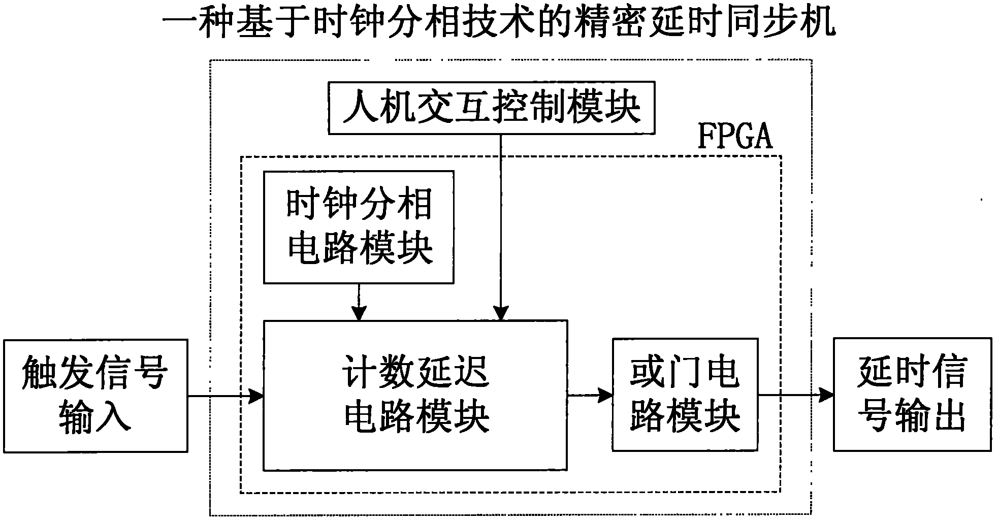
  • Clock phase-splitting technology-based precise digital time delay synchronous machine and time delay method
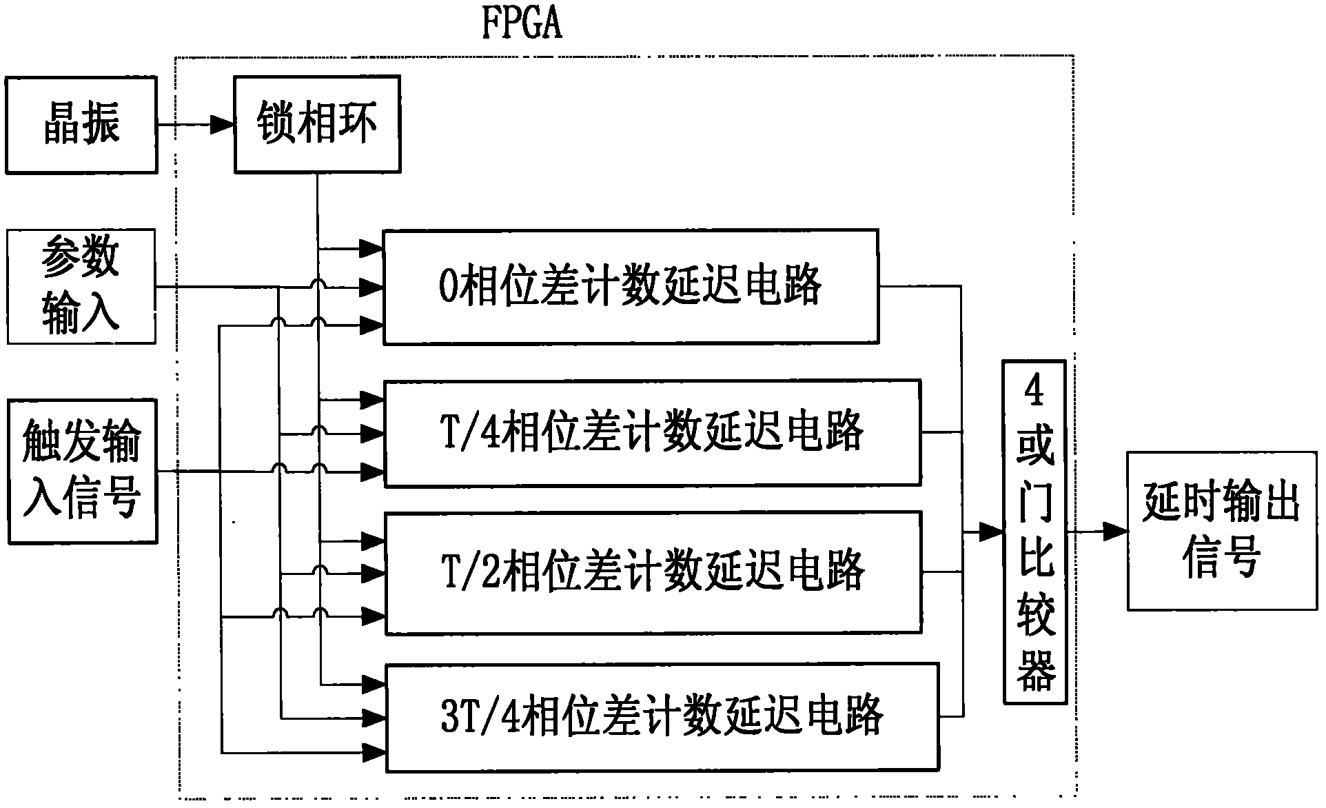
  • Clock phase-splitting technology-based precise digital time delay synchronous machine and time delay method
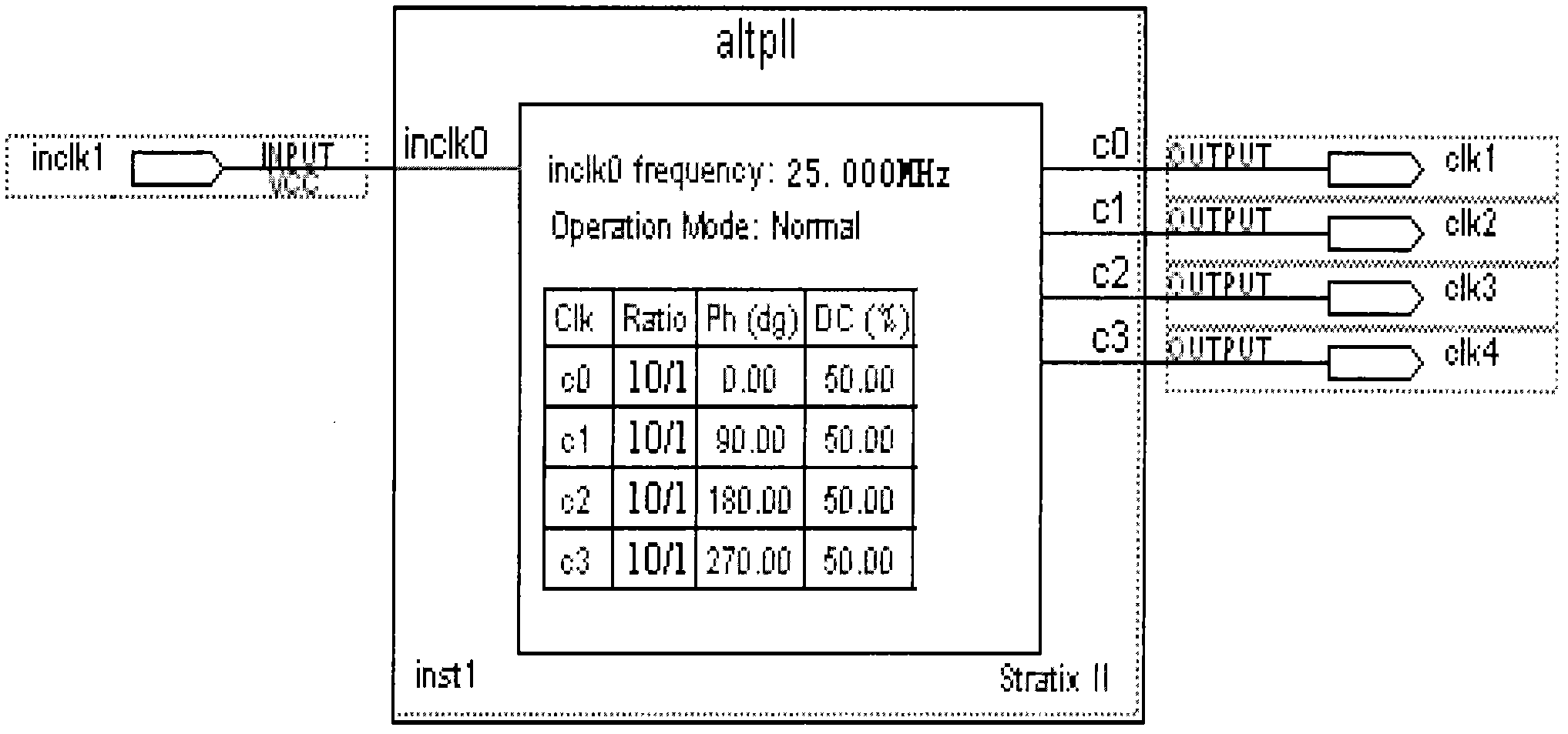
  • Clock phase-splitting technology-based precise digital time delay synchronous machine and time delay method

Examples


Embodiment Construction

[0020] In order to make the object, technical solution and advantages of the present invention clearer, the present invention will be further described in detail below in conjunction with the accompanying drawings and embodiments. It should be understood that the specific embodiments described here are only used to explain the present invention, not to limit the present invention.

[0021] System principle analysis: the present invention adopts clock phase-splitting technology, utilizes VHDL language and schematic diagram mixed programming design to complete the precision digital time-delay synchronous machine design based on clock phase-splitting technology by FPGA (field programmable gate array). In this design, a low-frequency, high-precision crystal oscillator is used as a clock source, and the low-frequency clock passes through a phase-locked loop (PLL) to obtain a high-stability, low-jitter phase-splitting clock. Using a multi-stage phase-splitting clock, the clock with ...


PUM


Abstract

The invention relates to a digital time delay synchronous machine and a time delay method, in particular to a clock phase-splitting technology-based precise digital time delay synchronous machine and a time delay method. In order to solve the problems on complexity in setting up a charge-discharge constant-current source and a phase detection and phase compensation circuit in the prior art, the invention provides a precise digital time delay synchronous machine based on a clock phase-splitting technology, which ensures that precise time delay compensation of the time delay synchronous machine is achieved, and circuit setting-up is simple and reliable and is low in power consumption. In the technical scheme, the precise digital time delay synchronous machine comprises a front-end signal conditioning module, a delay synchronous control module, a signal driving module and an upper computer control module, and the delay synchronous control module comprises a clock phase-splitting circuit module, a counting delay circuit for accomplishing counting and data comparison and a communication interface module. Before synchronous signals enter each path, the digital time delay synchronous machine is applied to carry out predelay to compensate the nonuniformity of each path of system so that the output of each system is in an occasion of the synchronous signals.

Description

technical field [0001] The invention relates to a digital time-delay synchronous machine and a time-delay method, in particular to a precision digital time-delay synchronous machine and a time-delay method based on clock phase separation technology. technical background [0002] In the physical test of multi-channel systems, it is often required that the signals of each system reach a certain circuit node at the same time, but because the circuit components and installation processes used by each system cannot be completely consistent, a group of synchronous signals passes through each system. After the delay, it becomes an asynchronous signal, which requires an instrument to do a pre-delay before the synchronous signal enters each channel to compensate for the inconsistency of each system, so that the output of each system is a synchronous signal, which is Delay sync machine. Trigger error, delay step and delay range are important technical indicators of delay synchronous ...

Claims


Application Information

Patent Timeline
Patent Type & Authority Applications(China)
IPC IPC(8): H03K5/13H03K5/00H03K5/01H03K5/135H03K5/14
Inventor 叶超代刚高平马成刚曹宁翔龙燕黄斌任青毅冯宗明赵娟李玺钦于志国梁川马勋马军邓维军李亚维黄雷丁明军吴红光冯莉立巨李晏敏王浩王卫张振涛贾兴谢敏曹科峰
Owner INST OF FLUID PHYSICS CHINA ACAD OF ENG PHYSICS
Learn More