Construction method for spanning railway, highroad or 6KV alive power line without using spanning frame when expanding optical cable of new lines

A live line and spanning frame technology, applied in the direction of optical fiber/cable installation, etc., can solve the problems of complex geographical environment, high construction difficulty, increased cost, etc., and achieve the effects of improving economic benefits, reducing construction costs, and saving costs

Inactive Publication Date: 2009-04-08
DAQING OILFIELD CO LTD
View PDF0 Cites 0 Cited by
  • Summary
  • Abstract
  • Description
  • Claims
  • Application Information

AI Technical Summary

Problems solved by technology

[0003] Such projects often have complex geographical environments, cross multiple live lines, and need to build a large number of spanning frames.
The construction is difficult and dangerous, which increases the cost virtually

Method used


Image

  • Construction method for spanning railway, highroad or 6KV alive power line without using spanning frame when expanding optical cable of new lines
  • Construction method for spanning railway, highroad or 6KV alive power line without using spanning frame when expanding optical cable of new lines

Examples


Embodiment 1

[0019] Embodiment 1. On-site survey: survey the height, width, crossing angle, terrain of the crossing point, etc. of the crossing power line, and determine the setting plan without erecting the spanning frame.

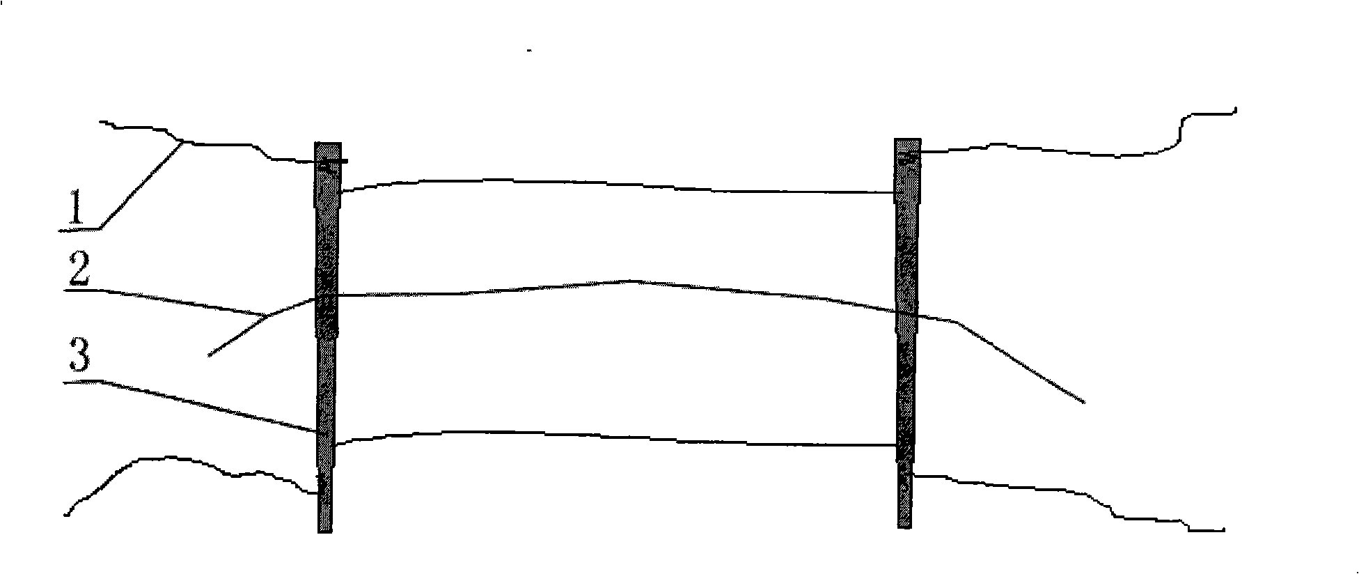
[0020] 1. First, assemble a temporary spanning frame on the ground according to the distance between the two sides of the original line and the spanning distance between the live line and the two sides;

[0021] 2. Assembly of the temporary spanning frame: connect two scaffolding poles with insulating ropes to form a rectangular spanning structure, and then connect one insulating rope for fixing to the two ends of each scaffolding pole. Reserve an insulated traction rope, reserve the traction rope to ride on the two scaffolding poles, and reserve the traction rope long enough to touch the ground at both ends;

[0022] 3. According to the installation position of the temporary spanning frame, nail 4 fixed ground anchors on the ground.

[0023] 4. After the temporary s...

Embodiment 2

[0028] Embodiment 2, take crossing the railway as an example:

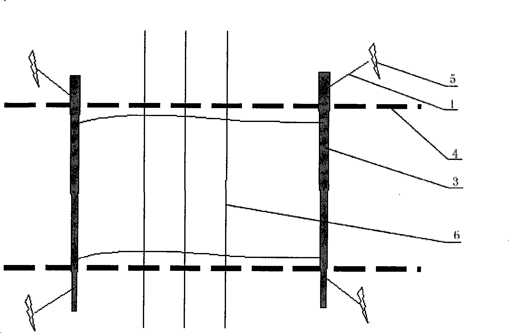
[0029] 1. First, according to the distance between the two sides of the original line, assemble a temporary spanning frame on the ground: connect the two scaffolding rods with insulating ropes to form a rectangular spanning structure, and then connect 4 fixed insulating wires to the two ends of the two scaffolding rods. An insulated traction rope is reserved between the two scaffolding poles. As shown in the picture:

[0030] 2. According to the installation position of the temporary spanning frame (that is, the width of the railway), drive 4 fixed ground anchors on the ground.

[0031] 3. After the temporary spanning frame is assembled, first use the insulating measuring rope (thinner) to throw over the side phase of the newly built line, and use this insulating measuring rope to pull the insulating ropes on the side of the two scaffolding poles across the two sides of the original line. The two sides of the or...


PUM


Abstract

The invention discloses a construction method when setting optical cables on a new line, which does not need to put up crossing brackets when crossing the railways, roads or 6kv live lines. The method comprises the following steps: (1), a temporary crossing bracket is assembled on the ground; (3), 4 fixing anchor blocks are knocked in the ground; (4), the temporary crossing bracket is assembled and then is dragged on an original line and is put up on the bottom of the two sides; (5), the temporary crossing bracket is dragged above the lines which are spanned, and the distance is adjusted; (6), 4 insolating ropes at the end part of a barling are fixed on the temporary anchor blocks, thus leading the two sides of the insolating ropes reserved in the middle to land the ground; (7), when setting the optical cables, one end of the insolating rope reserved is bound with the end parts of the optical cables, and the other end thereof leads the optical cables to cross the crossing brackets; (8), at last, the optical cables are fastened and the crossing brackets are withdrawn, the construction is finished. The construction method can effectively save the cost, lower the risk and improve the working efficiency.

Description

Technical field: [0001] The invention relates to a construction method for laying out optical cables on new lines in the field of oil field electric power, in particular to a construction method for laying out optical cables across railways, highways or 6,000-volt electrified lines in new lines without erecting spanning frames. Background technique: [0002] In recent years, with the continuous development of oil fields, the requirements for the stable operation of optical cables have become higher and higher. Most substations have adopted the method of optical cable data transmission to realize communication with the ESC and other substations. Some substations and power plants have failed to realize the ring network and resource sharing, so the optical cable erection project will also become the key work of our future construction. [0003] Such projects often have complex geographical environments and span multiple live lines, requiring the construction of a large number o...

Claims


Application Information

Patent Timeline
Patent Type & Authority Applications(China)
IPC IPC(8): G02B6/48G02B6/46
Inventor 丁修生谭庆宏张贵仁张明杰
Owner DAQING OILFIELD CO LTD
Why Eureka
Try Eureka