
Automatic temperature-control metal electric heating membrane

A metal electric heating film and self-controlling temperature technology, applied in electric heating devices, ohmic resistance heating, electrical components, etc., can solve the problems of random heating of local temperature, exceeding the standard, etc., and achieve a simple structure, low cost, and improved reliability. Effect

Inactive Publication Date: 2009-04-08
栾松
View PDF0 Cites 2 Cited by
  • Summary
  • Abstract
  • Description
  • Claims
  • Application Information

AI Technical Summary

Problems solved by technology

However, since multiple temperature sensors cannot be arranged on the entire electrothermal film, this temperature control circuit is only suitable for metal electrothermal films with uniform surface temperature, such as geothermal electrothermal films, etc. The problem of exceeding the standard

Method used


Image

  • Automatic temperature-control metal electric heating membrane
  • Automatic temperature-control metal electric heating membrane
  • Automatic temperature-control metal electric heating membrane

Examples


Embodiment 1

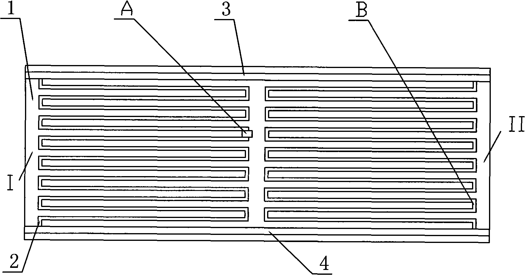
[0014] Example 1 as figure 1 , figure 2 Shown: Same as the prior art, there is a double-layer insulating film 1, a conductive line 2 is built in the double-layer insulating film 1, and an input bus 3 and an input bus 4 are connected to the conductive line 2, which are different from the prior art It is to directly lead out the wire on the conductive line 2 of unit I as the potential detection point A, and the potential reference point B only provides a reference value for the potential detection point A, which can be as follows figure 1 As shown, it is arranged on the conductive line 2 of another unit II, and may also be arranged on the insulating film 1, the input bus 4, etc. of another unit II. The signal processing circuit can be the same as the prior art, such as signal comparison circuit, signal amplification circuit, analog / digital conversion circuit, microprocessor and OR gate and other circuits; the driving execution circuit can be circuits such as relays. When the ...

Embodiment 2

[0015] Example 2 as image 3 Shown:

[0016] Same as the prior art, there is a double-layer insulating film 1, and a conductive circuit 2 is built in the double-layer insulating film 1, and an input bus 3 and an input bus 4 are connected to the conductive circuit 2. What is different from the prior art is that it is conductive The potential detection point A is directly set on the line 2, the potential detection point A is connected to the input terminal of the comparator I in the signal processing circuit, and the potential reference point B is the comparison voltage set at the other input terminal of the comparator I, the potential detection point A and potential reference point B are compared by a comparator, and its output is connected to the drive execution circuit through other circuits of the signal processing circuit (signal amplification circuit, analog / digital conversion circuit, microprocessor and OR gate).

Embodiment 3

[0017] Example 3 as Figure 4 , 5 Shown:

[0018] Same as the prior art, there is a double-layer insulating film 1, and a conductive circuit 2 is built in the double-layer insulating film 1, and an input bus 3 and an input bus 4 are connected to the conductive circuit 2. What is different from the prior art is that it is conductive There is a potential detection point A on the line 2, and the voltage reference point B is the contact point of the series resistor R1 and the adjustable resistor R2, the other end of the resistor R1 is connected to the input bus 3, and the other end of the adjustable resistor R2 is connected to the input bus 4 connected. The outputs of the potential detection point A and the potential reference point B are connected with the drive execution circuit through the signal processing circuit as in the first embodiment.

[0019] Potential detection point A divides the conductive line 2 of the metal electrothermal film into two sections to form resistan...


PUM


Abstract

The invention discloses a self temperature-control metal electric heating membrane which is provided with a double-layer insulating membrane. A conductive circuit is arranged in the double-layer insulating membrane. An input bus is connected with the conductive circuit. The conductive circuit is provided with a potential detection point A and is also provided with a potential reference point B additionally. The output of the potential detection point A and the potential reference point B is connected with a drive executing circuit by a signal processing circuit. When any area of the metal electric heating membrane is under a double-side heat preservation state, the potential of the potential detection point can rise along with the increase of the temperature of the area to ensure that the potential difference between the potential detection point and the potential reference point is changed; the potential variable is processed by the signal processing circuit and passes through a drive control circuit, thereby being capable of realizing outage. The invention can prevent a part of the metal electric heating membrane from being overheated as people lean against the metal electric heating membrane, avoids the damage to the insulating membrane thus caused, improves the reliability of the metal electric heating membrane, and prolongs the service life of the metal electric heating membrane. The invention also has the advantages of simple structure, low cost, easy control and the like at the same time.

Description

Technical field: [0001] The invention relates to a metal electric heating film, in particular to a self-controlling temperature metal electric heating film which can monitor itself in real time and realize automatic control (power off) when the temperature of any point exceeds a standard value. Background technique: [0002] Metal electric heating film is provided with metal (alloy) conductive lines between insulating films (PET), and two input buses (high and low potential) are connected to the conductive lines. At present, it has been widely used in geothermal, electrothermal painting and film heating. devices and other fields. In order to reduce heat loss, insulation materials are usually installed on the back of the metal electric heating film, so that most of the heat generated is emitted and radiated to the front, and its surface temperature is designed to be 80-90°C. However, if both sides are in a state of heat preservation, the surface temperature can reach 170-180...

Claims


Application Information

Patent Timeline
Patent Type & Authority Applications(China)
IPC IPC(8): H05B3/36H05B1/02
Inventor 栾松栾文彦栾竹
Owner 栾松
Learn More