Water gate dipper type shunting energy dissipating rushing-proof technology
What is Al technical title?
Al technical title is built by PatSnap Al team. It summarizes the technical point description of the patent document.
A bottom current energy dissipation and energy dissipation technology, which is applied in water conservancy projects, sea area engineering, coastline protection, etc., can solve unsatisfactory stress conditions and anti-cavitation ability, unsatisfactory flow state, and sensitivity to water depth changes, etc. problems, to achieve good economic benefits and application prospects, reduce the excavation depth, and the effect of less engineering
Inactive Publication Date: 2012-09-05
FUJIAN PROVINCIAL INVESTIGATION DESIGN & RES INST OF WATER CONSERVANCY & HYDROPOWER
View PDF0 Cites 0 Cited by
Summary
Abstract
Description
Claims
Application Information
AI Technical Summary
This helps you quickly interpret patents by identifying the three key elements:
Problems solved by technology
Method used
Benefits of technology
Problems solved by technology
It has been used in stilling ponds of a number of water conservancy projects such as Hexi Power Station in Hunan, Taoshan Reservoir in Heilongjiang, Shahezi Reservoir in Jilin, Wudao Reservoir, Donglin Reservoir, Liuyang Reservoir, Xiaoshihe Reservoir, etc. However, there are still the following deficiencies in the energy dissipation of the stilling bucket and the energy dissipation of the stilling pier: for the energy dissipation of the stilling bucket, the bucket has a high requirement for the downstream water depth, and the change of the flow state is very sensitive to the change of the water depth. Most of the flow states cannot reach the ideal state; as for the energy dissipation of the stilling pier, because the pier body is directly impacted by the water flow, although the body shape has been improved several times, the stress conditions and anti-cavitation ability are not satisfactory
[0004] Retrieval of relevant materials including Chinese patents shows that there are no application examples and related reports of sluice-type shunt flow energy dissipation and anti-scour technology at home and abroad
Method used
Image
Click on the blue label to locate the original text in one second.
Reading with bidirectional positioning of images and text.
Examples
Embodiment 1
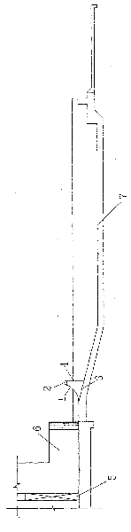
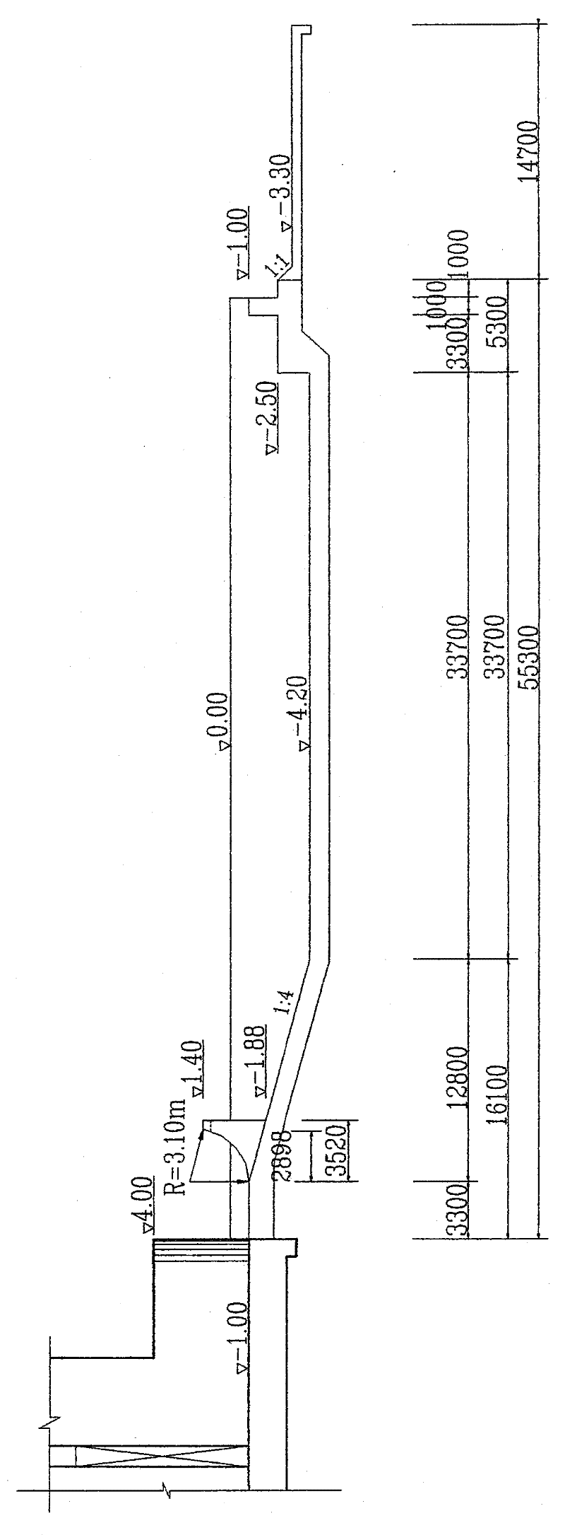
[0038] Such as figure 1 The curve 1 of the water-facing surface of the bucket type diverter pier shown is designed as a cylindrical surface with a radius of 3.1m;
[0039] The design of pier top 2 is:
[0040] The upper bottom is 2.7m long, the lower bottom is 3.5m long, and the horizontal trapezoidal shape is 0.622m high;
[0041] Pier bottom 3 is designed as:
[0042] The slope section of 1:4 is connected with the horizontal section of the stilling pool.
[0043] The pier back water surface 4 is designed as:
[0044] A vertical rectangular shape with a width of 3.5m and a height of 2.88m or 3.28m;
[0045] The sluice gate 5 is a wide 8.5m, and a height is a flat steel gate of 7.5m;
[0046] Gate pier 6 is a cuboid with a length of 18m and a thickness of 2.5m, and two ends are columns with a radius of 1.25m;
[0047] The stilling pool 7 is a 1:4 slope surface on one side and a deep 3.2m pool.
PUM
Abstract
The invention discloses a novel sluice bucket type flow-dividing and energy-dissipation scour prevention technology. The technology comprises five parts, i.e., the overall design thought, the type selection of a section simulating hydraulic model, the verification of an integral simulating hydraulic model, the observation of an original model, and the comparison of economic technology, and the like. The design of the invention has eight most important key parts, i.e., the frontal edge width B1 of a pier, the top width B2 of a tail end, the bottom width B3 of the tail end, the inverted arc radius R of the upstream face of the pier, the flip shot angle Theta, the pier height P, the number of the pier, and the top space B4 between the tail ends of the piers, and the like. The design method of the sluice bucket type flow-dividing and energy-dissipation scour prevention technology is divided into two major parts, i.e., the body form design and the distribution of the piers. The bucket type flow-dividing pier designed in the way is characterized by low downstream water level, high energy consumption rate in ordinary flow flood discharging working condition, small stilling pool depth, short pool length, less workamount, low investment, and the like.
Description
technical field [0001] The invention relates to a design method of hydraulic energy dissipation, a key technology in the design of water conservancy and hydropower sluices. Specifically, it is a new sluice bucket type diversion energy dissipation and anti-scouring technology. technical background [0002] The sluice is one of the most important structures in dam construction. It has the dual functions of retaining water and releasing water. The functions of the sluice include flood control, irrigation, power generation, water supply, shipping and so on. Therefore, in addition to being safe and reasonable in structure, it must also have good hydraulic characteristics. The sluice-type diversion energy dissipation and anti-scour technology belongs to the category of new technology for flood discharge and energy dissipation of dams in water conservancy and hydropower projects, and the content involves the most important buildings in dam construction. Flood discharge and energy ...
Claims
Application Information
Patent Timeline
Application Date:The date an application was filed.
Publication Date:The date a patent or application was officially published.
First Publication Date:The earliest publication date of a patent with the same application number.
Issue Date:Publication date of the patent grant document.
PCT Entry Date:The Entry date of PCT National Phase.
Estimated Expiry Date:The statutory expiry date of a patent right according to the Patent Law, and it is the longest term of protection that the patent right can achieve without the termination of the patent right due to other reasons(Term extension factor has been taken into account ).
Invalid Date:Actual expiry date is based on effective date or publication date of legal transaction data of invalid patent.
Patent Type & Authority Patents(China)
IPC IPC(8): E02B8/06
Inventor 杨首龙何承农吴秋华何光同林琳
Owner FUJIAN PROVINCIAL INVESTIGATION DESIGN & RES INST OF WATER CONSERVANCY & HYDROPOWER