Split type die for press machine, manufacturing method and forging cutting teeth thereof

A technology for presses and bucket teeth, which is applied in the field of split molds for presses, manufacturing and forging bucket teeth, which can solve the difficulty of disengaging the bucket teeth from the mold after forging, the difficulty of demoulding the bucket teeth after forging, and prevent the forging of bucket teeth Development and other issues, to achieve the effect of improving mechanical properties and wear resistance, improving production efficiency, and improving performance

Inactive Publication Date: 2009-04-15
陈宏毅
View PDF0 Cites 14 Cited by
  • Summary
  • Abstract
  • Description
  • Claims
  • Application Information

AI Technical Summary

Problems solved by technology

Compared with the casting workpiece, the mechanical properties and wear resistance of the forged workpiece known in the metal material processing theory should be improved by more than 30%, so that the research of forged bucket teeth has been put on the agenda, but due to the special shape and structure of forged bucket teeth, the press During die forging, the bucket teeth are completely filled with the mold so that it is very difficult for the bucket teeth to disengage from the mold after forging, resulting in low production efficiency; the technical obstacle that the bucket teeth are difficult to demould after forging prevents the development of forged bucket teeth products

Method used


Image

  • Split type die for press machine, manufacturing method and forging cutting teeth thereof

Examples


Embodiment Construction

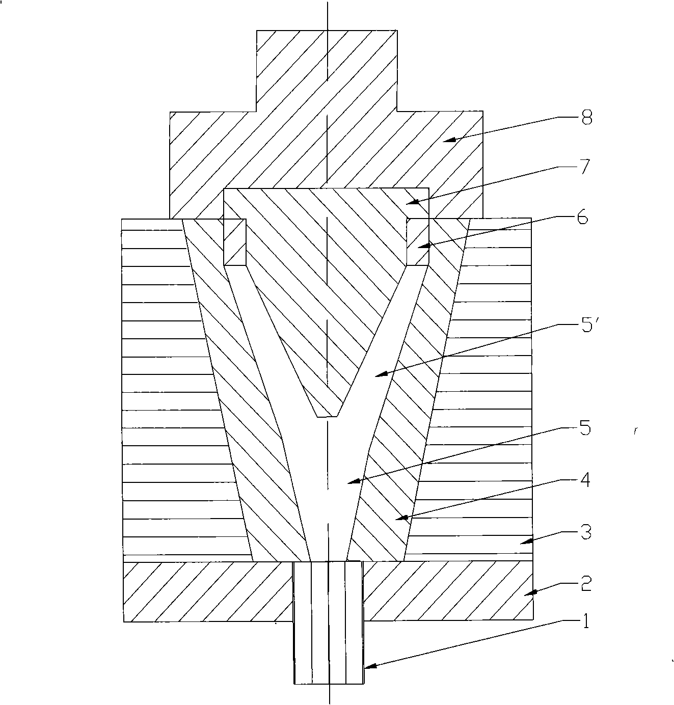
[0022] Depend on figure 1 As shown, the split mold for the press is divided into upper and lower split parts. The upper split body is composed of the upper punch sleeve 8 and the punch 7 embedded in the lower end. The upper split body can move up and down; the lower split body The overcoat 3 is fixedly connected to the pad plate 2, and the left and right split inner tire molds 4 are installed in the outer jacket 3. The upper part of the inner tire mold 4 is equipped with a disengagement square sleeve 6, and the size of the inner circle of the disengagement square sleeve 6 is Consistent with the size of the heel of the punch 7, the shape of the inner ring of the square sleeve 6 can be rectangular or square or other shapes required by the project; Driven by pressure transmission. When the punch upper cover 8 carries the punch 7 and is fully inserted into the square cover, an inverted "herringbone"-shaped bucket tooth mold cavity 5 is formed between the punch 7 and the inner tir...


PUM

PropertyMeasurementUnit
tensile strengthaaaaaaaaaa

Abstract

The invention discloses a split type mould used for a press, a manufacturing method and a forging bucket tooth thereof, which utilizes the split type mould to solve the technical problem of demoulding. The adopted mould is divided into an upper separated body and a lower separated body, the upper separated body consists of a punch head upper cover and a punch head embedded at the lower end of the punch head upper cover; the lower separated body is formed by that an outer sleeve is fixedly connected on a backing plate and internally installed with a tube mold of the separated body, and a disconnecting square sleeve is installed at the upper part inside the tube mold; and an ejector rod is installed in the central hole of the backing plate. The manufacturing method comprises the following steps: the punch head is utilized for hammering the blank so as to carry out foring compression in the tube mold, the punch head moves upwards when the press returns to the original position, the disconnecting square sleeve prevents the forging bucket tooth form moving so as to disconnect the punch head and the forging bucket tooth, the ejector rod ejects the forging bucket tooth and the tube mold of the separated body upwards, the tube mold is divided into two blocks along the outer sleeve, and the forging bucket tooth carries out demoulding automatically. The invention solves the problem of the automatic demoulding of the bucket tooth by foring compression; the mechanical property and the wear-resisting property of the forging bucket tooth are improved by more than 30 percent compared with that of a casting bucket tooth, especially when being used in severe conditions such as mines and the like, the forging bucket tooth has more superior performances.

Description

technical field [0001] The invention relates to a special forging bucket tooth, a manufacturing method and a mold, in particular to a split mold for a press, a manufacturing method and a forging bucket tooth. Background technique [0002] Bucket teeth are mainly used in construction machinery such as excavators. There are performance requirements for bucket teeth such as strength, toughness, hardness, and wear resistance, as well as internal organization requirements such as no air bubbles, shrinkage cavities, looseness, and sand holes, etc., and size and shape. The above requirements are related to the installation performance and service life of bucket teeth. Therefore, in terms of material selection, physical and chemical performance indicators should be met, and in terms of manufacturing methods, appropriate processing techniques should also be selected. The bucket teeth used in large quantities are usually manufactured by sand casting method. The mechanical properties ...

Claims


Application Information

Patent Timeline
Patent Type & Authority Applications(China)
IPC IPC(8): E02F9/28B21K1/00B21J5/02B21J13/02
Inventor 陈宏毅
Owner 陈宏毅
Why Eureka
Try Eureka