

Excimer lamps
A technology of excimer lamps and particles, applied in the field of excimer lamps, can solve problems such as uneven illumination distribution, and achieve uniform illumination distribution, consistent fluidity, and uniform dispersion
- Summary
- Abstract
- Description
- Claims
- Application Information
AI Technical Summary
Problems solved by technology
Method used
Image

Examples
experiment example 1
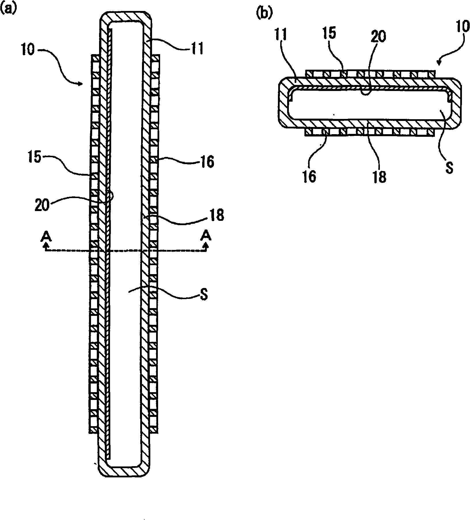
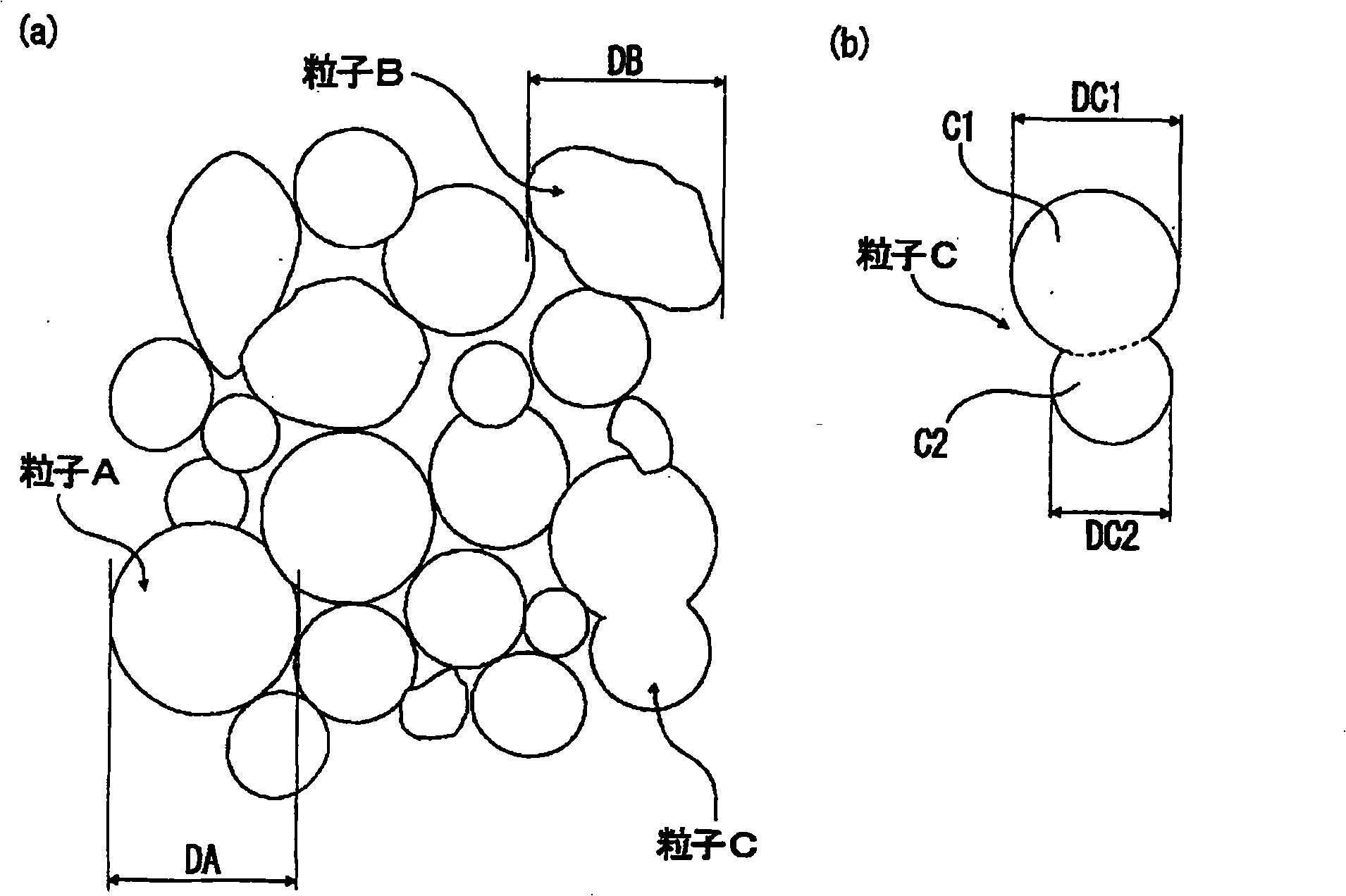
[0053] according to figure 1 In the configuration shown, eight types having the same configuration were produced except that the ratio D1 / D2 of the central particle diameter D1 of the silica particles in the ultraviolet reflection film to the central particle diameter D2 of the alumina particles was changed according to Table 1 below. excimer lamps. The basic configuration of each excimer lamp is as follows.
[0054] (Constitution of Excimer Lamp)
[0055] The size of the discharge vessel is 10 x 40 x 900 mm and the thickness is 3 mm.
[0056] The gas for discharge enclosed in the discharge vessel was xenon gas, and the enclosed amount was 50 kPa.
[0057] The dimensions of the high voltage supply electrode and the ground electrode are 30×800 mm.
[0058] The light emitting length of the excimer lamp is 800 mm.
[0059] The ratio of particles having a central particle size among the silica particles constituting the ultraviolet reflection film was 50%. The ratio of part...
experiment example 2
[0067] Except that the emission length was 1600mm, it had the same configuration as Experimental Example 1, and the ratio D1 / D2 of the central particle diameter D1 of the silica particles of the ultraviolet reflection film to the central particle diameter D2 of the alumina particles was determined according to the following Table 2. Instead, eight types of excimer lamps were manufactured, and the same experiment as in Experimental Example 1 was performed to investigate the relative illuminance distribution of each excimer lamp. The results are shown in Table 2 below.
[0068] [Table 2]
[0069]
[0070] From the above results, it can be confirmed that regardless of the size of the light emission length of the excimer lamp, an ultraviolet reflection film is formed by mixing silica particles whose central particle diameter is 0.67 times or more the central particle diameter of alumina particles as silica particles. The excimer lamps 9 to 14 can make the relative illuminance ...
experiment example 3
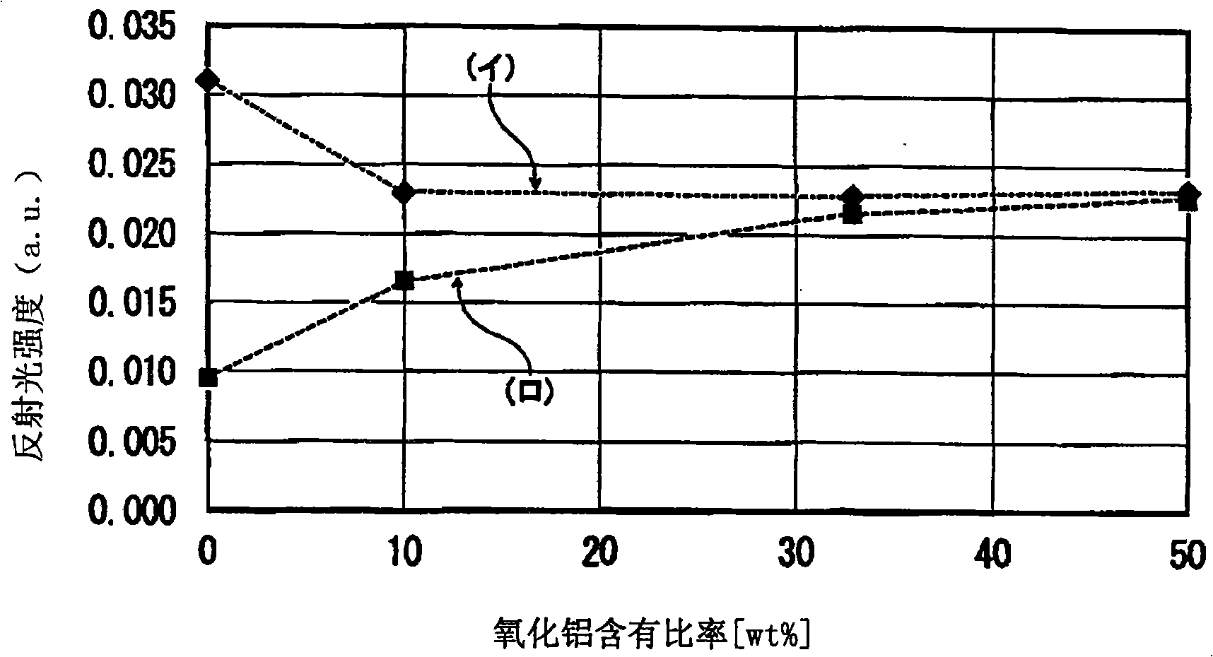
[0072] The ultraviolet reflective film is formed of silica particles with a central particle diameter (D1) of 0.3 μm and alumina particles (D1 / D2=1.00) with a central particle diameter (D2) of 0.3 μm. The ultraviolet reflective film whose ratio was changed to 0wt%, 10wt%, 33wt%, and 50wt% was formed in the film thickness of 30 micrometers on the flat silica glass base material, and four kinds of test pieces were produced.
[0073] And, for each test piece, when the ultraviolet reflective film was heated to 1000°C, [ image 3 The straight line (イ) shown by the dotted line in image 3 The reflected light intensity of each light with a wavelength of 170 nm of the straight line (□) shown by the dotted line in . The results are shown in image 3middle. Here, 1000°C, which is the heating temperature of the ultraviolet reflective film, corresponds to the firing temperature when forming the ultraviolet reflective film, and 1300°C corresponds to the heating temperature when plasma a...
PUM
| Property | Measurement | Unit |
|---|---|---|
| Thickness | aaaaa | aaaaa |
| Film thickness | aaaaa | aaaaa |
| Central particle size | aaaaa | aaaaa |
Abstract
Description
Claims
Application Information