Compressor unit

A compressor and pressure technology, applied in engine components, pump components, electromechanical devices, etc., can solve the problems of the destruction of insulating parts, the explosive expansion of the suction medium, etc., to avoid channel blockage, improve practicability, and reduce complexity. Effect

Inactive Publication Date: 2009-04-15
SIEMENS AG
View PDF1 Cites 16 Cited by
  • Summary
  • Abstract
  • Description
  • Claims
  • Application Information

AI Technical Summary

Problems solved by technology

[0005] Another risk is the porous insulation of the stator, which is partly absorbed in the area surrounding the washout by the conveying medium that is in contact with the stator as cooling medium, so that in the event of a sudden drop in pressure, for example during a work interruption, suction can result Explosive expansion of the medium in the pores of the insulation and thus destruction of the insulation
[0006] These known disadvantages with a high risk for the availability of the compressor unit are unacceptable especially for underwater work, for example for natural gas extraction

Method used


Image

  • Compressor unit
  • Compressor unit

Examples


Embodiment Construction

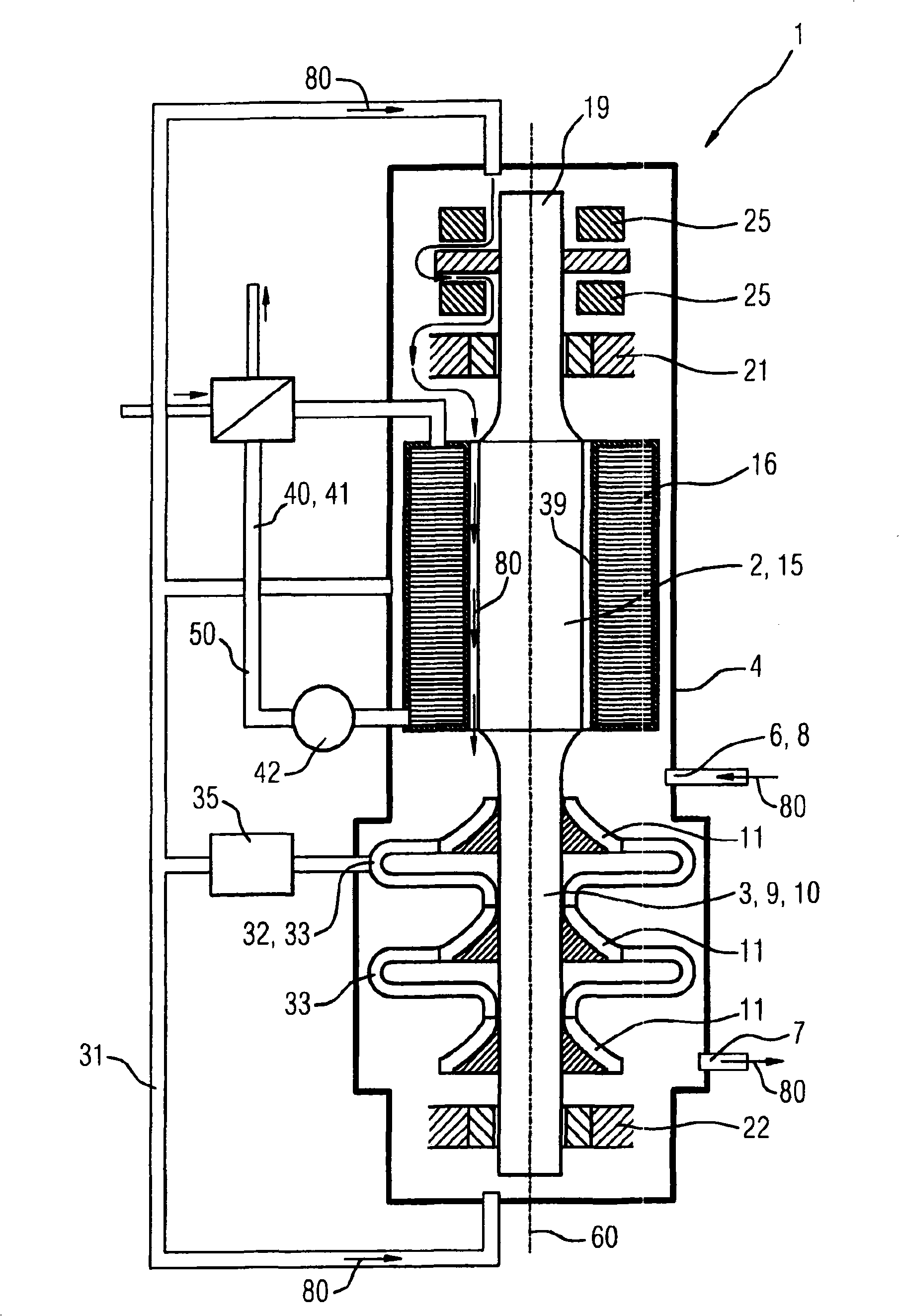
[0021] figure 1 A section through a compressor unit 1 according to the invention is shown schematically, which comprises, as essential components, a motor 2 and a compressor 3 in a gas-tight housing 4 . The housing 4 protects the motor 2 and the compressor 3 . The housing 4 is provided in the transition region from the motor 2 to the compressor 3 with an inlet 6 and an outlet 7 , through which the fluid to be compressed is sucked in via the inlet 6 by means of a suction connection 8 and the compressed fluid is allowed to flow through the outlet 7 Walk.

[0022] The compressor unit 1 is arranged vertically in operation, wherein the motor rotor 16 of the motor 2 is united by the compressor rotor 9 of the compressor 3 into a common shaft 19 , which rotates about a common vertical axis of rotation 60 .

[0023] The motor rotor 15 is supported in a first radial bearing 21 at the upper end of the motor rotor 15 .

[0024] The compressor rotor 9 is supported in a lower position by...


PUM


Abstract

The invention relates to a compressor unit (1), in particular for underwater operation, wherein the stator (16) of the motor (2) is connected to a separate cooling means (40). It is an object of the invention to provide a cooling means for the stator of the electric motor, which cooling means firstly affords excellent operational reliability and secondly does not require any exchange of materials with the surroundings during operation. To this end, there is provision for the cooling means (40) to be configured in such a way that there is a natural circulation of a cooling medium (56) in the cooling means (40) of the stator (16) under operating conditions. One decisive advantage of the compressor unit (1) according to the invention lies in the fact that the separate cooling means (40) of the stator (16) can be adapted precisely to the operating conditions of the latter and, in particular, firstly the high power loss and secondly the sensitivity of this component can be taken into consideration.

Description

technical field [0001] The invention relates to a compressor unit for compressing a transport medium, in particular for underwater work, comprising a compressor and an electric motor comprising a stator and a rotor. Background technique [0002] The latest developments in the field of compressor manufacturing are also several in the submerged installations of large compressors that should be used to transport natural gas. Due to the special working conditions, and especially because the operability is severely restricted, both for maintenance purposes and via supply lines, this technical field is confronted with great challenges. The relevant ambient conditions in no way permit an exchange of substances between the device to be installed and the surrounding sea water. Additionally, seawater is an aggressive medium and encounters extreme pressure and temperature conditions at different water depths. There is also the requirement that, on the one hand, the device should have...

Claims


Application Information

Patent Timeline
Patent Type & Authority Applications(China)
IPC IPC(8): F04D17/12F04D25/06F04D29/58H02K9/00
CPCF16C37/00F16C32/0489F04D29/584F04D17/122F16C37/005H02K9/197F04D17/12F04D25/06F04D25/0686F04D29/5806F16C2360/44F04D29/058
Inventor T·尼休斯
Owner SIEMENS AG
Why Eureka
Try Eureka