Valve assembly for connecting a heat exchanger of a hot water discharging device to a district heating system

A technology of valve device and heat exchanger, which is applied in the field of valve device and can solve the problems of high cost

Active Publication Date: 2009-04-15
DANFOSS AS
View PDF1 Cites 2 Cited by
  • Summary
  • Abstract
  • Description
  • Claims
  • Application Information

AI Technical Summary

Problems solved by technology

[0003] However, the cost of manufacturin

Method used


Image

  • Valve assembly for connecting a heat exchanger of a hot water discharging device to a district heating system
  • Valve assembly for connecting a heat exchanger of a hot water discharging device to a district heating system

Examples


Embodiment Construction

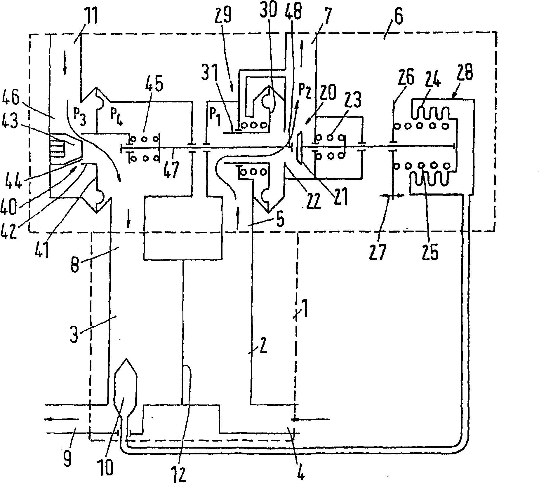
[0024] figure 1 A heat exchanger 1 with a primary side 2 and a secondary side 3 is shown schematically. The primary side 2 has an inlet 4 which is connected to a district heating system, not shown in detail. The primary side 2 also has an outlet 5 which is connected via a valve arrangement 6 to a return connection 7 of the district heating network.

[0025] The secondary side 3 has an inlet 8 for the inflow of water and an outlet 9 from which heated water can be drawn off. In the area of ​​the outlet 9 there is a temperature sensor 10, the function of which will be explained further below. The inlet 8 of the secondary side 3 is connected via a valve arrangement 6 to a water connection 11 for supplying cold water.

[0026] The heat exchange surface 12 is arranged between the primary side 2 and the secondary side 3 in a manner known per se, the principle of which is only shown here. In practice the heat exchange surface 12 has a much greater extension.

[0027] The valve de...


PUM


Abstract

Disclosed is a valve assembly (6) for connecting a heat exchanger (1) of a hot water discharging device to a district heating system. Said valve assembly (6) comprises a valve (20) which is located on a primary side and controls a flow of heat exchange fluid through a primary side (2) of the heat exchanger (1), and a pressure-controlled valve (40) that is located on a secondary side and acts upon a flow of process water through a secondary side (3) of the heat exchanger (1). The valve (20) located on the primary side can be actuated by the valve (40) located on the secondary side. In order to simplify the production of such a valve assembly, the valve (40) that is located on the secondary side is provided with an adjustable neutral opening (44).

Description

technical field [0001] The invention relates to a valve device for connecting a heat exchanger of a hot water extraction device to a remote heating network, the valve device having a primary side valve which controls the flow of heat transfer fluid through the heat exchanger flow on the primary side; the valve arrangement is also provided with a pressure-controlled secondary side valve which affects the flow of water through the secondary side of the heat exchanger, wherein the primary side valve can be manipulated by the secondary side valve . Background technique [0002] Such a valve arrangement is known from DE 19618093 C2. The valve element of the primary-side valve and the valve element of the secondary-side valve are connected to one another via an actuating rod. When water is diverted, the pressure at the outlet of the secondary side valve drops, causing the valve element of the secondary side valve to move towards the open position. At the same time, this also ca...

Claims


Application Information

Patent Timeline
IPC IPC(8): G05D16/06F24D10/00F16K7/12
CPCF24D10/003F24D19/1051Y02E20/14G05D16/0641Y02B30/17
Inventor 詹斯·J·莫尔比克
Owner DANFOSS AS
Why Eureka
Try Eureka