Water-oil separating system and method using centrifugation, gravitation, expansion composite principle

A technology for oil-water separation and oil-water separation, which can be used in immiscible liquid separation, earthwork drilling, and fluid production, etc., and can solve problems such as reduced processing efficiency.

Inactive Publication Date: 2009-04-22
INST OF MECHANICS - CHINESE ACAD OF SCI
View PDF0 Cites 17 Cited by
  • Summary
  • Abstract
  • Description
  • Claims
  • Application Information

AI Technical Summary

Problems solved by technology

[0005] The purpose of the present invention is to solve the above oil-water separation device using a single separation principle, when the parameters of the incoming liquid change during the separation process, the processing efficiency is significantly reduced, thereby providing a separation method using centrifugal, gravity, expansion, etc. The separation method is a combination of principles. This method is an effective way to increase separation efficiency, improve separation technology, and reduce the weight of the separator. It is suitable for both onshore oilfields and offshore oilfields, and has a good industrial application prospect.

Method used


Image

  • Water-oil separating system and method using centrifugation, gravitation, expansion composite principle
  • Water-oil separating system and method using centrifugation, gravitation, expansion composite principle
  • Water-oil separating system and method using centrifugation, gravitation, expansion composite principle

Examples


Embodiment 1

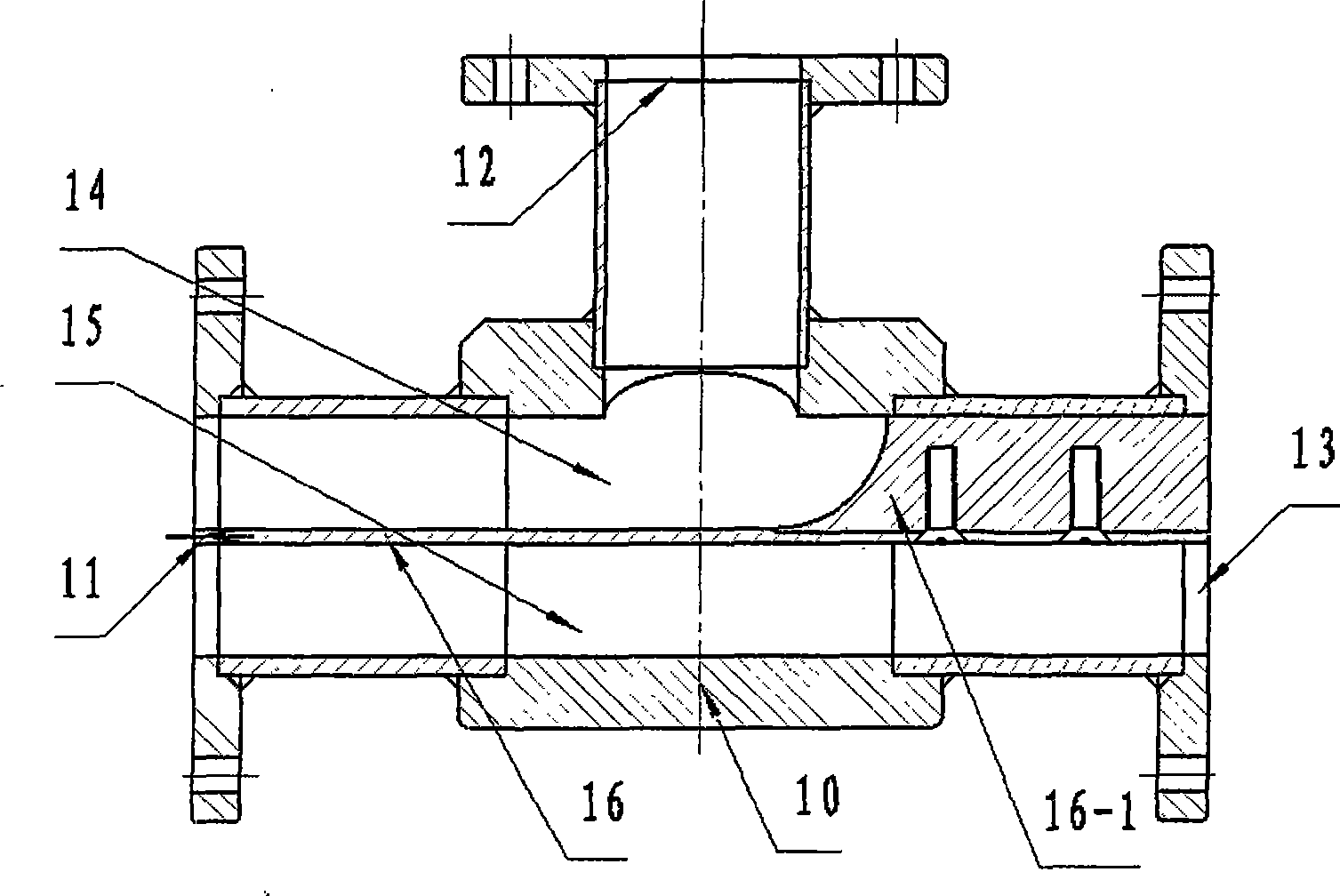
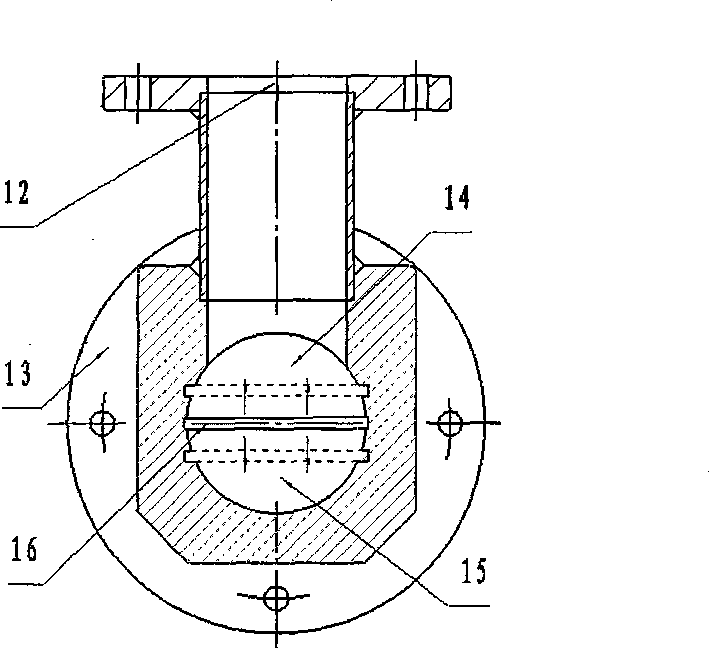
[0046] Referring to Fig. 1, make the first shunt 10 and the second shunt 20, the body of the shunt is a pressure-resistant vessel with a three-way tubular structure, and a liquid inlet 11 is provided on the pressure-resistant vessel, and the three-way pipe The nozzle on the left side is the liquid inlet 11, the nozzle on the right side of the three-way pipe is the lower liquid outlet 13, and the upper nozzle of the three-way pipe is the upper liquid outlet 12; Divider baffle 16 divides cavity into upper and lower two spaces, upper chamber 14 communicates with upper liquid outlet 12, lower chamber 15 communicates with lower liquid outlet (or horizontal liquid outlet) 13, and both layers of space are connected with inlet. The liquid port is connected. The end of the splitter is flush with the end of the liquid inlet. The splitter is located above one end of the nozzle on the right side of the tee pipe and has a plug 161 that closes the upper part of the nozzle. The longitudinal...

Embodiment 2

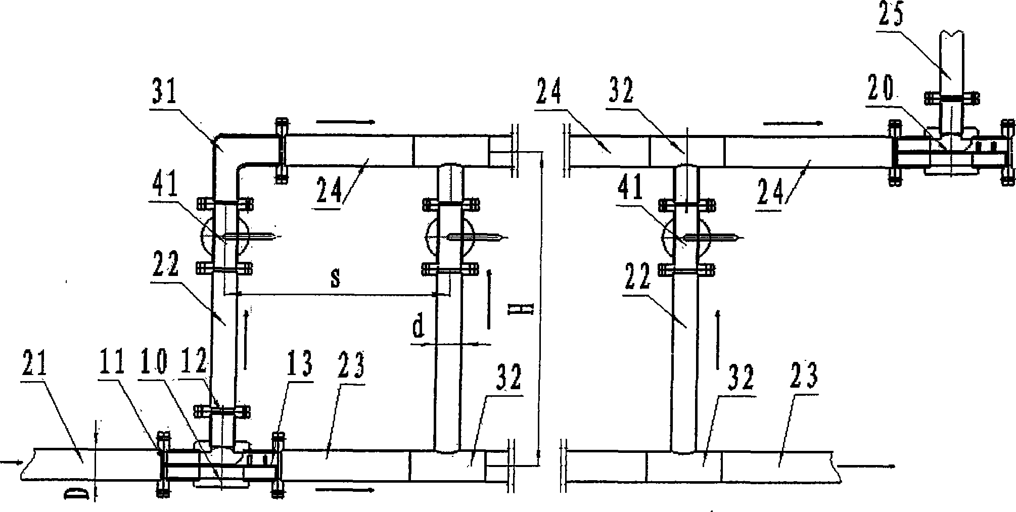
[0049] See Figure 1 and figure 2 , Make a T-shaped pipe separation device: T-shaped pipe 200 is made up of horizontal total liquid inlet pipe 21, upper horizontal pipe 24, lower horizontal pipe 23, vertical pipe 22, flow divider 10 (20) and valve 41. The horizontal main liquid inlet pipe 21 is connected to the incoming flow pipeline, the other end is connected to the inlet 11 of the flow divider 10, the upper outlet 12 of the flow divider is connected to the vertical pipe 22, the horizontal outlet 13 is connected to the lower horizontal pipe 23, and the upper end of the vertical pipe is connected to the valve 41. The other side of 41 is connected with the bottom opening 31 of the 90-degree elbow, and the elbow is connected with the upper horizontal pipe 24. N vertical tubes 22 are connected in parallel between the upper horizontal tube 24 and the lower horizontal tube 23 , thereby forming a T-shaped tube 200 . The T-shaped pipe is at least composed of a total liquid inlet pi...

Embodiment 3

[0051] refer to image 3 , make a helical tube separator: the helical tube main body 500 is a vertical structure, the helical tube main body 500 is fixed on the support 90 of the helical tube main body, the helical tube input pipe 51-port of the helical tube main body 500 is installed with an input pipe valve 42, Spiral pipe input pipe 55 one port installs output pipe valve 43; The total number of turns is 25, and the spiral pipe upper part of spiral pipe main body 500 has 4 circles to be band hole section 54, and the band hole section below is closed section 52; The number of small holes in the 3 circles from top to bottom is n 1 , n 2 , n 3 , the apertures are d 1 、d 2 、d 3 ;The number and diameter of circular holes should follow the following design criteria: n 1 ≤n 2 ≤n 3 , d 1 ≤d 2 ≤d 3 Have a circular hole 70 on each circle of the perforated section, the circular hole 70 begins to perforate from the outlet 1 / 4 circumference of the output pipe 55, and the circu...


PUM


Abstract

The invention relates to a combined type oil-water separating system for onshore treatment stations and offshore oil production platforms, wherein a liquid inlet and a liquid outlet of a current divider are communicated with a horizontal total liquid inlet pipe, a vertical pipe and a lower horizontal pipe; the vertical pipe is communicated with a bend pipe; the lower horizontal pipe is connected with an input port of a helical pipe, the helical pipe is connected with the inner part of a fourth separating box body, and communicated with a second settlement separating box body, and the top part of the helical pipe is communicated with the top part of a fourth settlement separating box body by a middle pipe; the outlet and the middle part of the bottom part of the side wall of the fourth settlement separating box body, which corresponds to the inlet, is provided with horizontal drain pipes and a horizontal oil discharge pipe respectively, and the other end of the horizontal oil discharge pipe penetrates the middle part of a third settlement separating box body; an upper horizontal pipe is communicated with a first helical pipe, the other outlet of the first helical pipe is connected with the inner part of the third settlement separating box body, and the bottom parts and the side walls of the top parts of the first and the third settlement separating box bodies are connected by pipes; the two horizontal drain pipes are provided with a water outlet pipe and an oil outlet pipe respectively.

Description

technical field [0001] The invention relates to a device and method for separating oil-water two-phase mixed liquid, in particular to a composite oil-water separation system and separation method applied to onshore and offshore oil production platforms. Background technique [0002] In many industries, such as petrochemical enterprises, oil-water separation equipment is an important production equipment. Separation technology is crucial to the development of the industry. [0003] The separation principles currently used are: gravity, centrifugation, filtration, electrostatic, demulsification, etc. The initial separation equipment generally adopts one separation principle for oil-water separation. In recent years, the combination of multiple separation principles for separation equipment is the development direction. For example, the patent publication number: CN2569538Y, a high-efficiency oil-water separator, describes a separation device that mainly adopts the principle ...

Claims


Application Information

Patent Timeline
Patent Type & Authority Applications(China)
IPC IPC(8): B01D17/02E21B43/34
Inventor 郑之初张军吴应湘郭军唐驰周永王立洋龚道童
Owner INST OF MECHANICS - CHINESE ACAD OF SCI
Why Eureka
Try Eureka