Tridimensional allocation plan of aluminium foil mill

A technology of aluminum foil rolling mill and configuration scheme, applied in metal rolling and other directions, can solve the problems of waste of land, large area and high construction cost, and achieve the effect of reducing construction cost and maintenance cost, saving plant area and reducing the amount of earthwork.

Inactive Publication Date: 2009-04-22
CHINA NON-FERROUS METALS PROCESSING TECH CO LTD
View PDF0 Cites 4 Cited by
  • Summary
  • Abstract
  • Description
  • Claims
  • Application Information

AI Technical Summary

Problems solved by technology

[0003] This configuration scheme has been used up to now, and it has a history of nearly 30 years in our country. A lot of experience has been accumulated in design, construction, and equipment installation, and it is easy to be accepted by the construction unit, but there are also disadvantages: (1) It occupies a large area Today, land resources are becoming increasingly tense, which not only wastes land, but also increases investment; (2) In the southern region where the groundwater level is relatively shallow, groundwater treatment is difficult and expensive during deep foundation construction

Method used


Image

  • Tridimensional allocation plan of aluminium foil mill
  • Tridimensional allocation plan of aluminium foil mill
  • Tridimensional allocation plan of aluminium foil mill

Examples


Embodiment 1

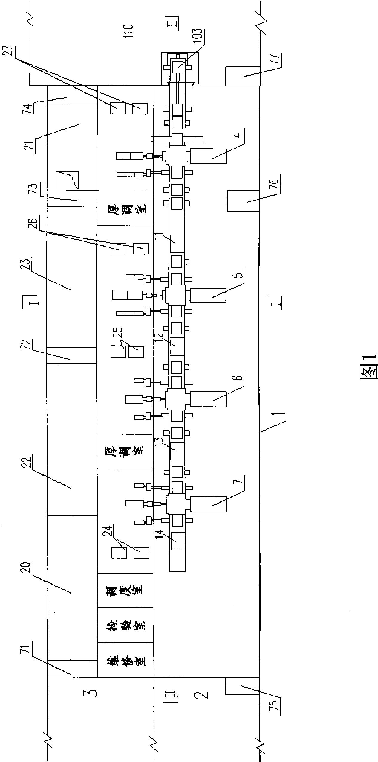
[0020] Rolling mill area 1 has a total length of 102m and a width of 36m. It is composed of rolling span 2 and rolling auxiliary span 3 with a width of 18m, both of which are two-story structures.

[0021] As shown in Figure 1, on the second-floor platform, from right to left, aluminum foil rough rolling mill 4, intermediate rolling mill 5, and two finishing mills 6, 7 are arranged in sequence. The electric control rooms 22 and 23 of the rolling mill, the hydraulic stations 24, 25, 26 and 27, and the oil mist purifiers 20 and 21 are placed in the rolling auxiliary span 3.

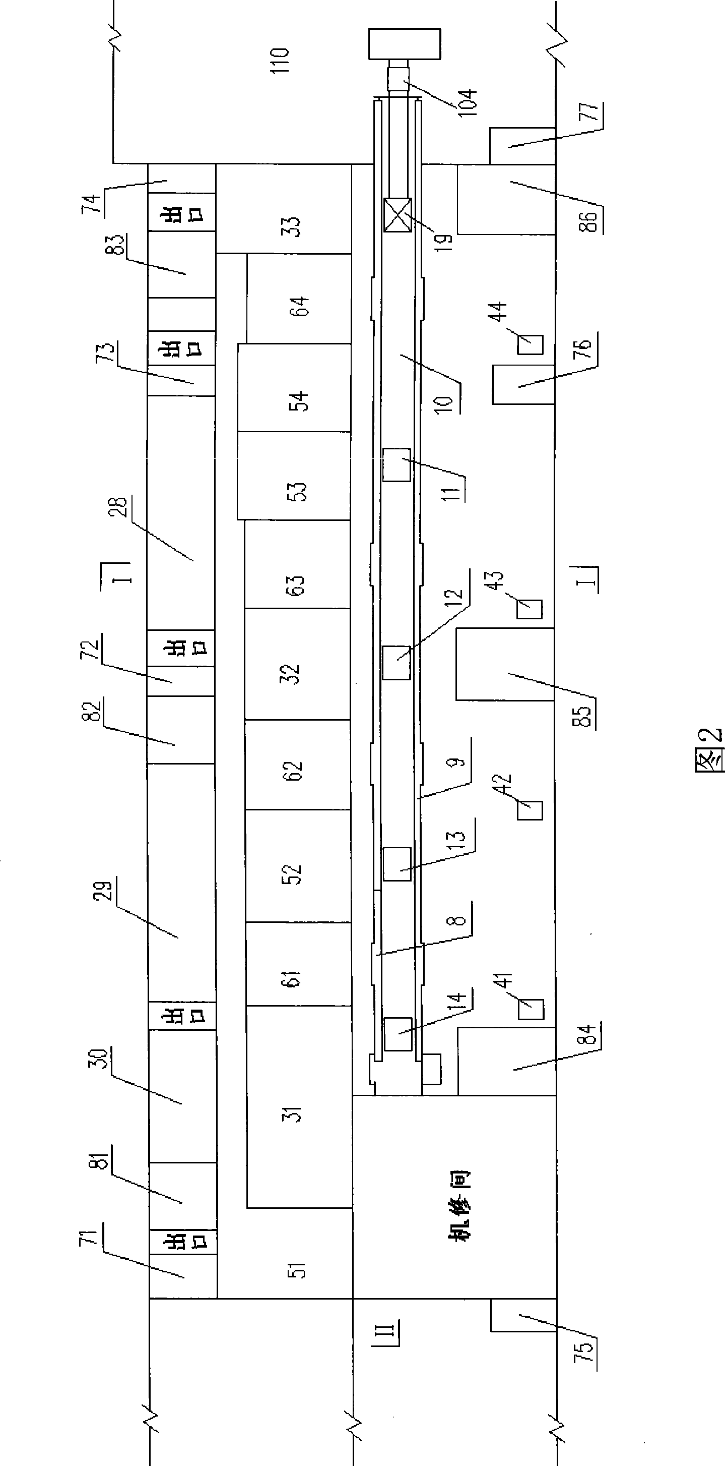
[0022] As shown in Figure 2, on the first floor plane, the transformer rooms 28 and 29 of the four rolling mills, the high-voltage distribution station 30, the process lubrication stations 31, 32 and 33, and the thin oil lubrication system stations 41, 42, 43, and 44, filter room 51, 52, 53 and 54, CO 2 Room 61, 62, 63, 64 and other auxiliary facilities.

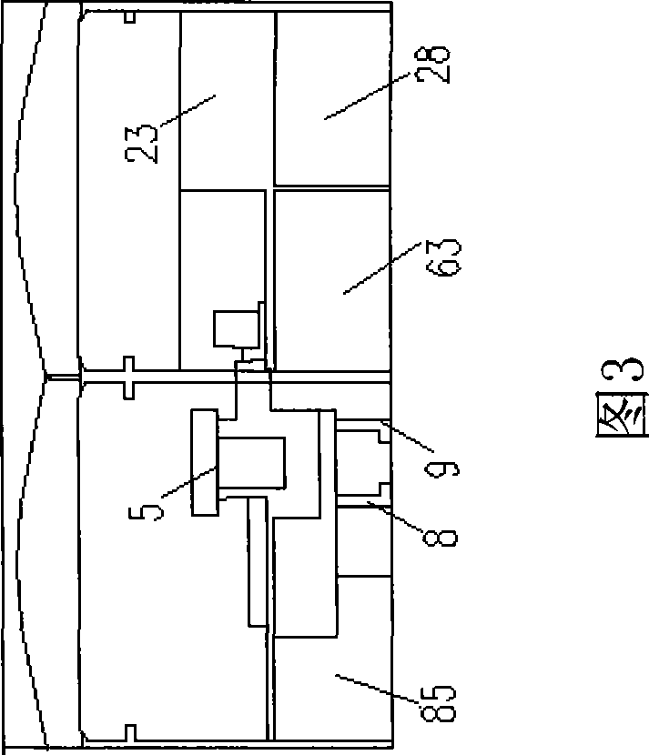
[0023] As shown in Figure 2 and Figure 3, there ...


PUM


Abstract

The invention discloses a stereo configuration proposal for an aluminum foil mill. The proposal comprises the following steps: placing the aluminum foil mill on a two-layer platform above the ground, and configuring auxiliary facilities such as a technical lubricating system and a thin oil lubricating system, a filter chamber, a CO2 chamber, an electric control chamber and the like and an auxiliary chamber between an upper layer and a lower layer of the aluminum foil mill; configuring the electric control chamber, an oil mist purifier and a hydraulic station of the mill in the rolling auxiliary span on the two-layer platform; configuring the auxiliary facilities of the technical lubricating system, the filter chamber, the thin oil lubricating system, a transformer chamber and the like of the aluminum foil mill on a plane of + / - 0.000 meter; and constructing two rows of concrete walls under a mill host of the rolling span, and forming a passage between the two rows of the concrete walls as a coiled material transportation passage. The configuration proposal has a compact mill area, saves floor area, reduces earth volume of underground engineering, avoids the problem of ground water leakage during deep foundation construction and usage, and reduces civil engineering cost and maintenance cost; and coiled material transportation in a rolling process can be controlled by computer program, so as to conveniently achieve three-level management of production in the future.

Description

technical field [0001] The invention relates to a configuration scheme of an aluminum foil rolling mill, specifically a three-dimensional configuration scheme of an aluminum foil rolling mill. Background technique [0002] The aluminum foil production process is aluminum foil blank - rough rolling - intermediate rolling - coiling - finishing rolling - slitting - annealing, which is also a mature process commonly used by aluminum foil processing plants. The aluminum foil rolling mill is the main equipment in the production of aluminum foil. The configuration plan adopted in the design of the aluminum foil processing plant or workshop is: the aluminum foil rolling mill is arranged on a plane of ±0.000m, and the auxiliary facilities such as rolling mill process lubrication and thin oil lubrication are arranged in the depth- Around 6.000m basement, mill auxiliary room (including filter room, CO 2 Room, electric control room, transformer room, fan room, etc.) are arranged betwee...

Claims


Application Information

Patent Timeline
Patent Type & Authority Applications(China)
IPC IPC(8): B21B1/40
Inventor 刘小玲刘劲波刘国金苏小新戴德美
Owner CHINA NON-FERROUS METALS PROCESSING TECH CO LTD
Why Eureka
Try Eureka