Speed variator with variable flow impeller

A transmission and impeller technology, which is applied to the components of pumping devices for elastic fluids, non-variable displacement pumps, machines/engines, etc., can solve the problems of easy failure, high price, complex structure, etc. Efficiency, low manufacturing cost, good energy saving effect

Inactive Publication Date: 2011-04-06
林英燮
View PDF0 Cites 0 Cited by
  • Summary
  • Abstract
  • Description
  • Claims
  • Application Information

AI Technical Summary

Problems solved by technology

However, there are some problems in their application: for example, the adjustment method of the inlet and outlet valves will cause large energy loss and easy to cause cavitation; the speed adjustment method generally requires the use of frequency converters, which are expensive and have power conversion losses; The adjustment method of the pump structure is complex in structure, prone to failure, and the adjustment range is not large in the existing designs.

Method used


Image

  • Speed variator with variable flow impeller
  • Speed variator with variable flow impeller
  • Speed variator with variable flow impeller

Examples


Embodiment Construction

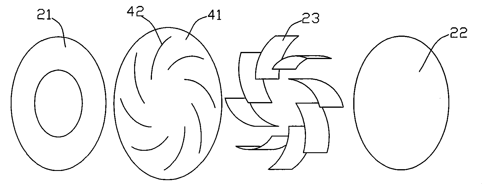
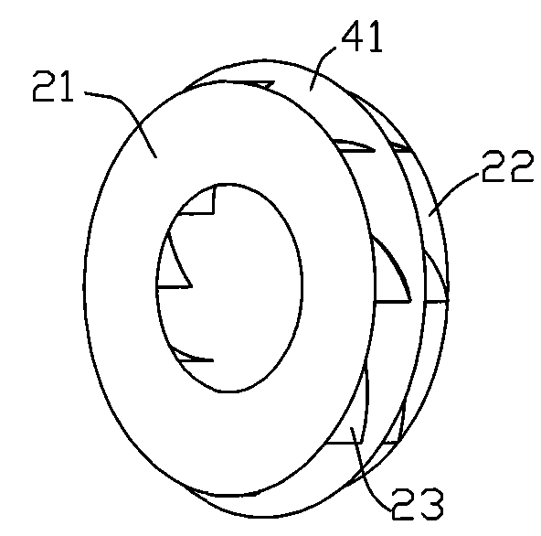
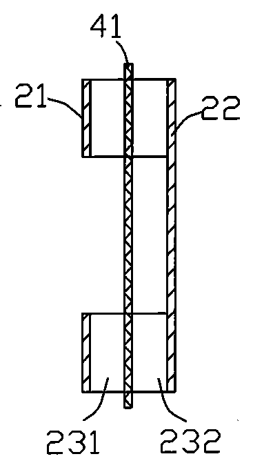
[0020] refer to Figures 1 to 3 , Figure 8 , Figure 9 , a transmission with a variable flow impeller, including a variable flow impeller, the impeller includes a front disk 21, a rear disk 22 and a blade 23 installed in the pump housing 1, the rear disk 22 is installed on the rotating shaft 31, and the blade 23 is covered A restrictor is provided, and the restrictor includes a partition 41, a slot 42 adapted to the thickness and shape of the blade 23 is provided on the partition 41, the blade 23 penetrates into the slot 42, and the partition 41 is connected with An adjustment device, the partition 41 can move forward and backward in the axial direction of the blade 23 driven by the adjustment device, and the partition 41 divides the blade 23 into an effective working area 231 and an ineffective working area 232 .

[0021] For a centrifugal impeller, if its diameter, blade length, curvature, thickness and other parameters are the same, the width of the blade determines the ...


PUM


Abstract

The invention relates to a variable flow impeller comprising a sealed pump shell, a main impeller and an output impeller respectively arranged in the left and right side of pump shell cavity. The main impeller is a variable flow impeller having a restrictor, the pump shell cavity is a ring cavity, and the main impeller and the output impeller have arc shape adaptive to the ring cavity shape. C shape cavities with opposite openings are respectively arranged on front disks of the main impeller and the output impeller. The main impeller and the output impeller are arranged in the pump shell, and the main impeller is controlled by the restrictor. The rotation speed of the output impeller can be changed as long as adjusting the flow of the variable flow impeller during work, thereby realizing the continuous adjustment of the rotation speed, effectively reducing the flow resistance during flow and improving work efficiency.

Description

technical field [0001] The invention relates to a transmission with a variable flow impeller. Background technique [0002] We use pumps everywhere in our work and life. Its function is to convert the mechanical energy of the prime mover into the pressure energy and kinetic energy of the fluid, so that the fluid can flow. Even water turbines like in hydroelectric generators are reversed uses of pumps. The impeller is the main component to realize the conversion of mechanical energy into fluid energy; it is responsible for the kinetic energy of the prime mover to drag the impeller to rotate, and the fluid can obtain pressure energy and kinetic energy by doing work on the fluid through the blades. [0003] In use, we often need to change the flow rate of the pump to meet the actual application requirements. The ways to change the flow rate of the pump generally include: adjusting the inlet and outlet valves, adjusting the speed and changing the structure of the pump. Howeve...

Claims


Application Information

Patent Timeline
Patent Type & Authority Patents(China)
IPC IPC(8): F04D29/24F04D29/18F04D29/00F04D15/00
Inventor 林英燮
Owner 林英燮
Why Eureka
Try Eureka