Double-frequency laser interferometry apparatus

A dual-frequency laser interference and measurement device technology, applied in measurement devices, optical devices, instruments, etc., can solve the problems of light can not be completely separated, large period error, large nonlinearity of heterodyne interferometers, etc., to improve anti-interference. Capability and measurement accuracy, avoid frequency aliasing, the effect of high subdivision accuracy

Inactive Publication Date: 2009-04-22
BEIJING CHANGCHENG METERING TEST TECH INST NO 1 GRP CO CHINA AVIATION IND
0 Cites 47 Cited by

AI-Extracted Technical Summary

Problems solved by technology

However, when the measurement accuracy is required to be at the nanometer level, the frequency mixing problem of the dual-frequency interferometer cannot be avoided when the longitudinal or transverse Zeeman laser is used, and the nonlinearity of the heterodyne interferometer is too large. The main reason is that the longitudinal and transverse Zeeman The laser polarization state radiated by the He-Ne ga...

Abstract

The invention relates to a double frequency laser interferometry device. The device comprises three parts, i.e. a light source light dividing light path part, a measuring light path part and a 90-degree phase difference signal receiving part. The light source light dividing light path part divides an incident light source into two lasers with frequency difference, and the two lasers enter the measuring light path part; after optical double path is realized by reflections by a measuring reflection mirror and a reference reflection mirror twice, the lasers are received by a photoelectric receiver of the 90 degrees phase difference signal receiving part. The invention adopts an acousto-optical frequency shifting device, so that a measured light and a reference light are separated at the beginning and frequency alias is avoided; and the interferometry device also adopts polarized light splitting and receiving technology, thus the interference signal with good contrast and high subdivision precision can be obtained.

Application Domain

Using optical means

Technology Topic

Optical pathOpto electronic +8

Image

  • Double-frequency laser interferometry apparatus
  • Double-frequency laser interferometry apparatus
  • Double-frequency laser interferometry apparatus

Examples

  • Experimental program(1)

Example Embodiment

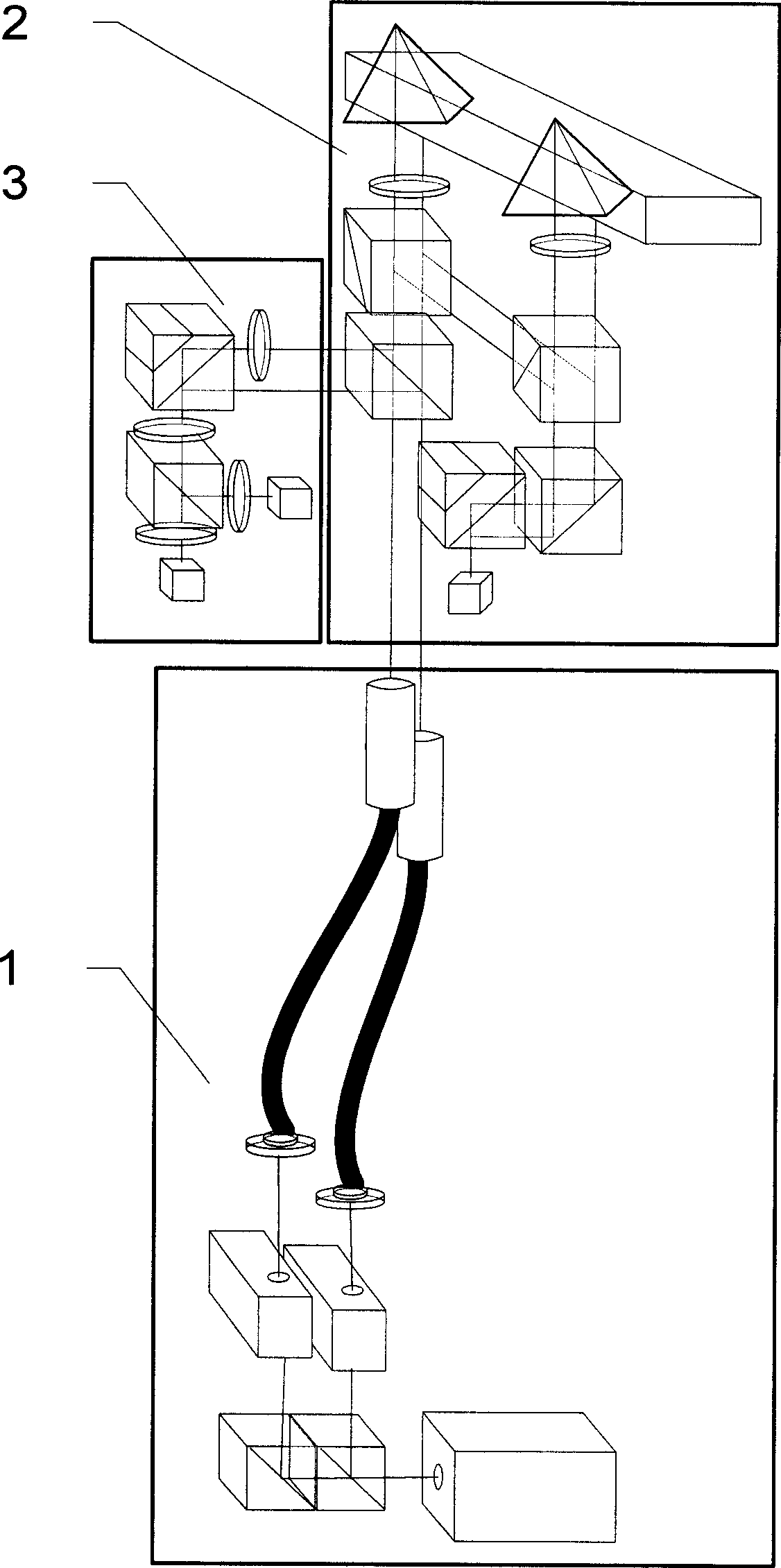
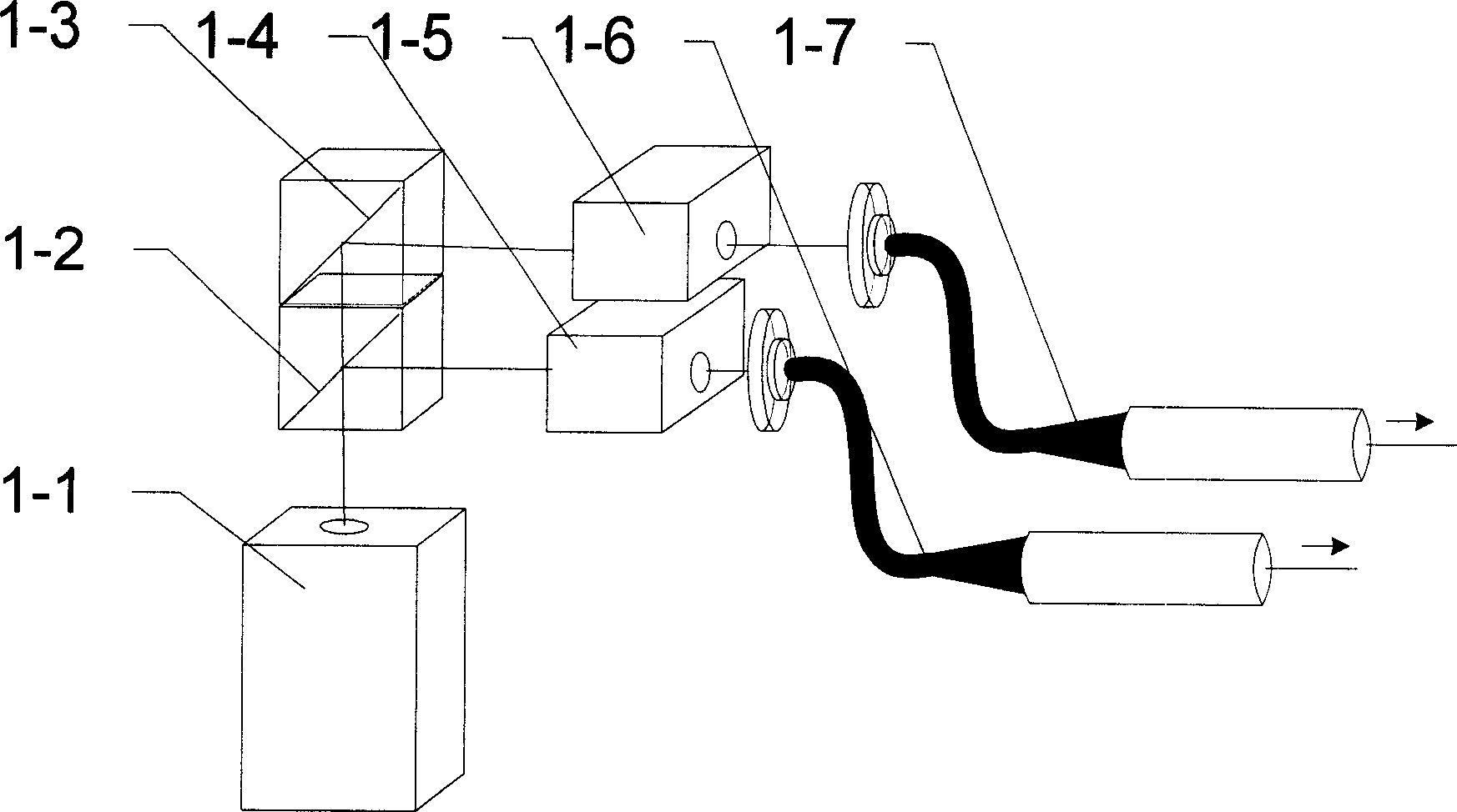
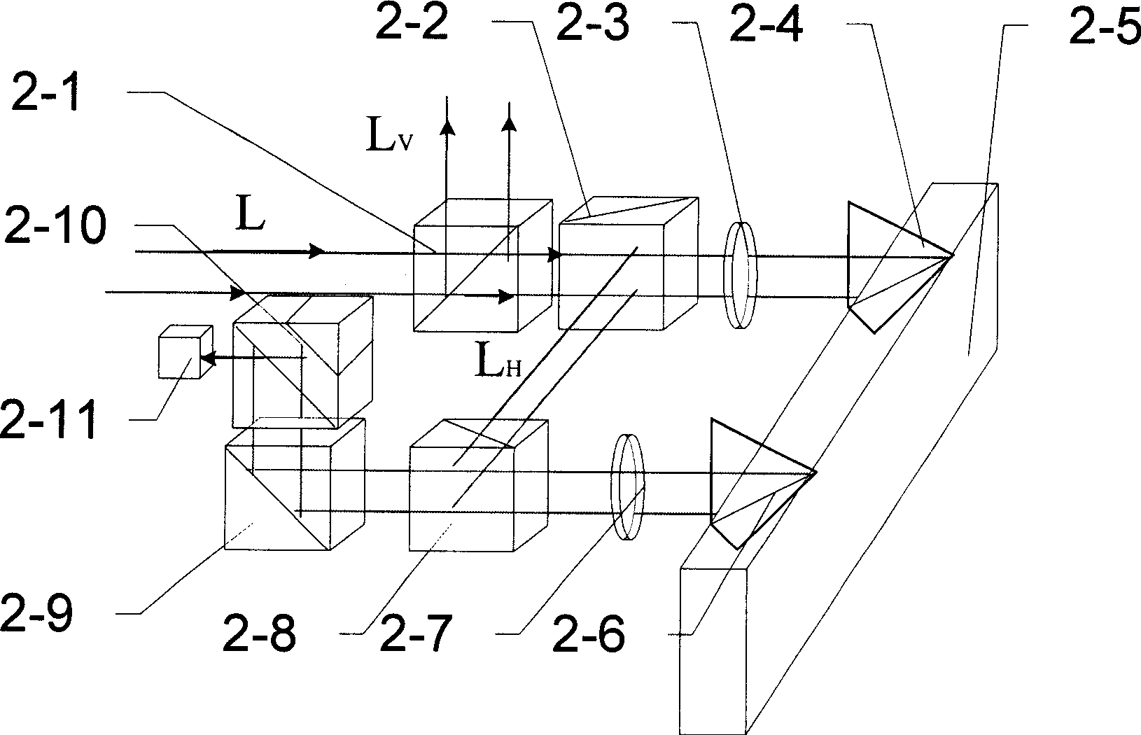
[0018] The device consists of three parts, including the light source beam splitting optical path part 1, the measuring optical path part 2 and the receiving signal part 3 with a phase difference of 90°. In the light source splitting optical path 1, a beam splitting prism 1-2, a right-angle mirror 1-3, an acousto-optic modulation 1-4 and 1-5, collimator 1-6 and 1-7, the incident light source is divided into two beams of laser beams with frequency difference, and enter the measurement optical path part 2; the measurement optical path part 2 is respectively put into the polarization beam splitter prism 2-1, 2-2 and 2-8, depolarizing beamsplitter prism 2-10, right-angle mirror 2-9, 1/4 wave plate 2-3 and 2-7, measured mirror 2-5 and reference reflection After mirrors 2-4 and 2-6 reflect twice to realize the optical multiplier, they are received by the photoelectric receiver 2-11; the received signal part 3 with a phase difference of 90° is sequentially placed into a 1/2 wave plate 3-1 and a beam splitting prism 3- 2. 1/4 wave plate 3-3, beam splitting prism 3-3, polarizing plates 3-5 and 3-6 and photoelectric receivers 3-7 and 3-8.
[0019] The beam-splitting prism 1-2 in the light source beam-splitting optical path part 1 is a depolarizing beam-splitting prism.
[0020] The two beams of light separated by the dichroic prism 1-2 respectively enter the AOMs 1-4 and 1-5 with frequency differences, and select the first-order diffracted lights of the two AOMs to generate two beams with fixed frequency differences linearly polarized light.
[0021] Acousto-optic modulators 1-4 and 1-5, collimators 1-6 and 1-7 are followed by polarization beamsplitter prisms 2-1, 2-2 and 2-8, depolarization beamsplitter prisms 2-10, 1/ 4 wave plates 2-3 and 2-7, so that the two beams of light separated by the light source are incident on the measuring mirror 2-5 and the reference mirrors 2-4 and 2-6 twice to obtain the beat frequency signal of the reference light.
[0022] The acousto-optic modulators 1-4 and 1-5 modulate two beams of laser light with different optical frequencies, and the polarization beam splitter 2-1 after the collimators 1-6 and 1-7 separates the light of each frequency into vibration states Two beams of linearly polarized light perpendicular to each other, in which lasers with different frequencies and the same polarization direction beat each other to obtain the reference signal of the dual-frequency interferometer.
[0023] The fast axis of the 1/4 wave plate 2-3 is placed at an angle of 45°, the incident linearly polarized light becomes circularly polarized light after passing through the 1/4 wave plate 2-3, and after being reflected by the mirrors 2-4 and 2-5, After passing through the 1/4 wave plate 2-3 again, it is converted into linearly polarized light perpendicular to the vibration direction of the incident ray polarized light, passes through the polarization beam splitter 2-8, and then passes through the reference mirror 2-6 and the measuring mirror 2-5 , to achieve an optical quadruple pass.
[0024] The receiving signal part 3 with a phase difference of 90° obtains two beams of linearly polarized light with the same polarization direction from the polarization beam splitter 2-1, and one beam of linearly polarized light is converted into a polarized beam with the original polarization by the 1/2 wave plate 3-1. The linearly polarized light that is perpendicular to each other is converted into two beams of circularly polarized light with the opposite direction of rotation through the 1/4 wave plate 3-3, and then divided into two beams of circularly polarized light that are mixed with the opposite direction of the polarization state through the depolarization beam splitter 3-4 Polarized light, two beams of light are received by photoelectric receivers 3-7 and 3-8 through polarizers 3-5 and 3-6 respectively.
[0025] The fast axis of the 1/2 wave plate 3-1 is placed at an angle of 45° so that the incident linearly polarized light passes through the 1/2 wave plate 3-1 and becomes linearly polarized light perpendicular to the original polarization state.
[0026] The fast axis of the 1/4 wave plate 3-3 is placed at an angle of 45°, so that the incident linearly polarized light becomes circularly polarized light after passing through the 1/4 wave plate 3-3.
[0027] The optical axes of the two polarizers 3-5 and 3-6 are placed at an angle of 45° to achieve a reference signal phase difference of 90°.
[0028] In the light source splitting device 1, the laser light emitted by the He-Ne laser 1-1 with high frequency stability and high degree of polarization is divided into two beams of light through the depolarization beam splitter prism 1-2, and one beam of light is reflected by the depolarization beam splitter prism 1-2 To the acousto-optic modulator 1-4, a beam of light is transmitted by the depolarizing beam splitter prism 1-2, and the transmitted light is reflected by the right-angle prism 1-3 to the acousto-optic modulator 1-5, and two laser beams with the same polarization state pass through the acousto-optic After the modulator 1-5 is diffracted, the first-order diffracted light becomes two laser beams with the same polarization state and different frequencies. A collimated laser beam is used to change the vibration direction of the electric vector of the light by rotating the collimator 1-6 and 1-7, so that the vibration direction of the electric vector is the same as image 3 The polarization axis of the polarizing beam splitter 2-1 (the polarization axis is perpendicular to the interference table) is 45°.
[0029] The measuring optical path part 2 is an optical device for realizing an optical quadruple pass.
[0030] The optical device for realizing the optical quadruple pass includes three polarizing beam splitting prisms 2-1, 2-2, 2-8 and a depolarizing beam splitting prism 2-10. At the polarizing beam splitting prism 2-1, the light beam L is decomposed into intensity equal vertical and horizontal two orthogonal linearly polarized components L V and L H. Reference beam L V Reflected by the polarizing beam splitting surface to the receiving optical path of the reference signal, the L transmitted by the polarizing beam splitting prism 2-1 HTwo beams of laser light enter next polarizing beam splitter 2-2, because the light of the polarization state transmitted through polarizing beam splitting prism 2-1 is all transmitted through polarizing beam splitting prism 2-2, enters 1/4 wave plate 2-3, because 1 The fast axis of the /4 wave plate 2-3 is 45° different from the optical axis direction of the transmitted light of the polarizing beam splitter prism 2-2, so the incident linearly polarized light becomes circularly polarized light after passing through the 1/4 wave plate 2-3, different The circularly polarized light of the frequency is respectively incident on the reference mirror 2-4 and the measuring mirror 2-5, and after being reflected by the reference mirror 2-4 and the measuring mirror 2-5, it returns according to the original optical path and passes through the 1/4 wave plate After 2-3, the polarization direction changes from circularly polarized light to linearly polarized light and the vibration direction is perpendicular to the incident direction of the incident linearly polarized light. Due to the change of polarization state, the linearly polarized light that returns to the polarization beam splitter 2-2 is polarized The light-splitting surface of the beam-splitting prism 2-2 is fully reflected, and after being incident on the polarization beam-splitter 2-8, it is still fully reflected by the light-splitting surface of the polarization beam-splitter 2-8, and becomes a circle after being incident on the 1/4 wave plate 2-7 Polarized light, in the same way, after the light of different frequencies is reflected by the reference mirror 2-6 and the measuring mirror 2-5, it passes through the 1/4 wave plate 2-7 again, and is completely transmitted by the light-splitting surface of the polarization beam splitter prism 2-8. It is reflected by the right-angle reflector 2-9 to the depolarizing beam splitting prism 2-10, and after being respectively reflected by the beam splitting surface and the reflecting surface of the depolarizing beam splitting prism 2-10, two laser beams of different frequencies meet, and the signal carrying the measurement information is received by the photoelectric Receiver 2-11 receives.
[0031] Figure 4 In order to realize the phase difference of 90° by the optical method, the receiving signal part 3 is used.
[0032] After two beams of reference light with the same vibration direction and different frequencies enter the receiving signal part 3 with a phase difference of 90°, one beam of frequency light is directly incident on the polarization beam splitter prism 3-2 and is reflected by the beam splitting surface, and the other beam of frequency laser light passes through a 1 The /2 wave plate 3-1 is incident to the polarization beam splitter 3-2, wherein the feature of the 1/2 wave plate 3-1 is that the included angle between the fast axis of the wave plate and the X-axis direction is 45°, so that the 1/2 The polarization states of the laser at the frequency of the wave plate 3-1 and the laser at another frequency are perpendicular to each other, so that the linearly polarized light passing through the 1/2 wave plate 3-1 is transmitted and polarized on the beam-splitting plane of the polarization beam splitter prism 3-2 The reflection surface of the reflective coating of the beam splitting prism 3-2 is reflected. After the two beams meet at the polarization beam splitting prism 3-2, they enter the 1/4 wave plate 3-3 to form two beams of circularly polarized light with opposite rotation directions, and then pass through The depolarization beam splitter 3-4 enters the polarizer 3-5 and the polarizer 3-6 respectively after being split by the depolarization beam splitter 3-4, and the feature of the polarizer 3-5 and the polarizer 3-6 is that two polarizers The direction of the optical axis of the plate differs by 45°, so that the phase difference of the two beams of light passing through the polarizer 3-5 and the polarizer 3-6 is 90°, and is received by the receiver 3-7 and the receiver 3-8 respectively .

PUM

no PUM

Description & Claims & Application Information

We can also present the details of the Description, Claims and Application information to help users get a comprehensive understanding of the technical details of the patent, such as background art, summary of invention, brief description of drawings, description of embodiments, and other original content. On the other hand, users can also determine the specific scope of protection of the technology through the list of claims; as well as understand the changes in the life cycle of the technology with the presentation of the patent timeline. Login to view more.

Similar technology patents

Reducing image artifacts in images

PendingUS20200265570A1good resolutiongood contrast
Owner:CARL ZEISS MICROSCOPY GMBH

Method for selecting image data source in optical instrument

ActiveCN102006431Alarge dynamic rangegood contrast
Owner:江苏钜芯集成电路技术股份有限公司

Method for producing a support comprising an electronic device

InactiveCN102667823Aprinting performance is goodgood contrast
Owner:ARJO WIGGINS SECURITY SAS

GIS-based territorial space planning system and planning display equipment thereof

PendingCN114882793Agood contrastOrganize data and ease of use
Owner:山东纵阡规划设计有限公司

Contrast Dyes for Inkjet Lithographic Printing Plates

InactiveUS20090036638A1good contrast
Owner:AGFA NV

Classification and recommendation of technical efficacy words

  • good contrast

Fingerprint reading device and personal verification system

InactiveUS20050123176A1good contrastreduce influence
Owner:CANON KK

Optical compensator for liquid crystal display

ActiveUS20050190327A1good contrast
Owner:INNOLUX CORP

Digital radiography (DR) contrast balancing method and system

ActiveCN104200446Agood contrastreduce workload
Owner:SHENZHEN ANGELL TECH

Plasma facing experimental part with reference corner structure

InactiveCN102520125AEasy to processgood contrast
Owner:INST OF PLASMA PHYSICS CHINESE ACAD OF SCI

Positive light advertising board device

InactiveCN101739917Agood contrastAvoid afterglow
Owner:秦厚敬
Why Eureka
Try Eureka