Method and apparatus for detecting stress field of hoister roller

A detection method and hoist technology, applied in the direction of measuring device, measuring force, transmission system, etc., can solve the problems of inconvenient installation of sensors, inconvenient installation and maintenance of sensors, and difficult installation, etc., and achieve high communication speed and communication reliability. Power supply problems, the effect of convenient installation and maintenance

Inactive Publication Date: 2009-04-22
CHINA UNIV OF MINING & TECH
View PDF0 Cites 17 Cited by
  • Summary
  • Abstract
  • Description
  • Claims
  • Application Information

AI Technical Summary

Problems solved by technology

This method mainly has four defects: the transmission distance of wireless communication in the wellbore is short, and when the depth of the wellbore exceeds 500 meters, reliable communication cannot be achieved; the battery needs to be replaced regularly, which is inconvenient to maintain; the installation and maintenance of the sensor is inconvenient; the sensitivity of the tension sensor is low, The tension sensor will aggravate the fatigue wear of the wire rope, and the oil pressure sensor is only suitable for occasions where there is a hydraulic balance device between the lifting container and the wire rope
Sensors are difficult, expensive to develop, and difficult to install
It is also difficult to replace the sensor in time when it is destroyed
[0003] According to the above analysis, it can be found that the current method of reflecting the operating state of the hoist by detecting the tension of the hoisting wire rope mainly has the following defects: the installation of the sensor is inconvenient, and the maintenance of the detection system is difficult; the application of the detection system has certain limitations and cannot be applied to deep well detection; The battery-powered solution requires regular battery replacement, which is inconvenient to maintain; the existing sensors have problems such as high cost, low sensitivity, and damage to the wire rope

Method used


Image

  • Method and apparatus for detecting stress field of hoister roller
  • Method and apparatus for detecting stress field of hoister roller
  • Method and apparatus for detecting stress field of hoister roller

Examples


Embodiment 1

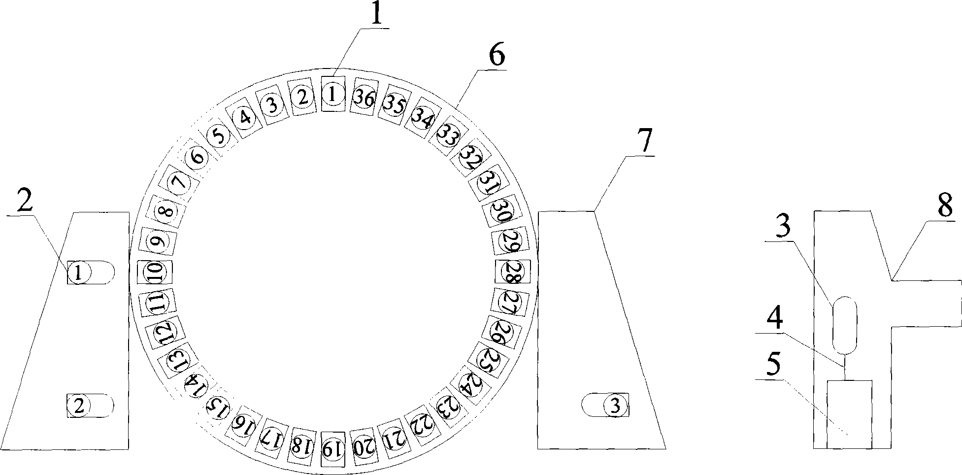
[0016] Embodiment 1: The device of the present invention includes a hoist drum, a brake seat, a stress wireless sensor node 1, an anchor node 2, a convergence node 3, a USB interface 4 and an industrial computer 5, and the brake seat is located on the outside of the hoist drum , the stress wireless sensor node is fixed on the hoist roller, the anchor node is fixed on the brake seat, the converging node is fixed on the shell of the hoist console, and the converging node is connected to the industrial computer through the USB interface.

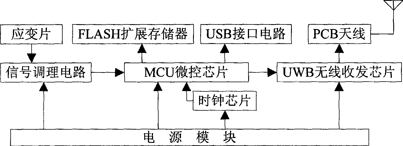
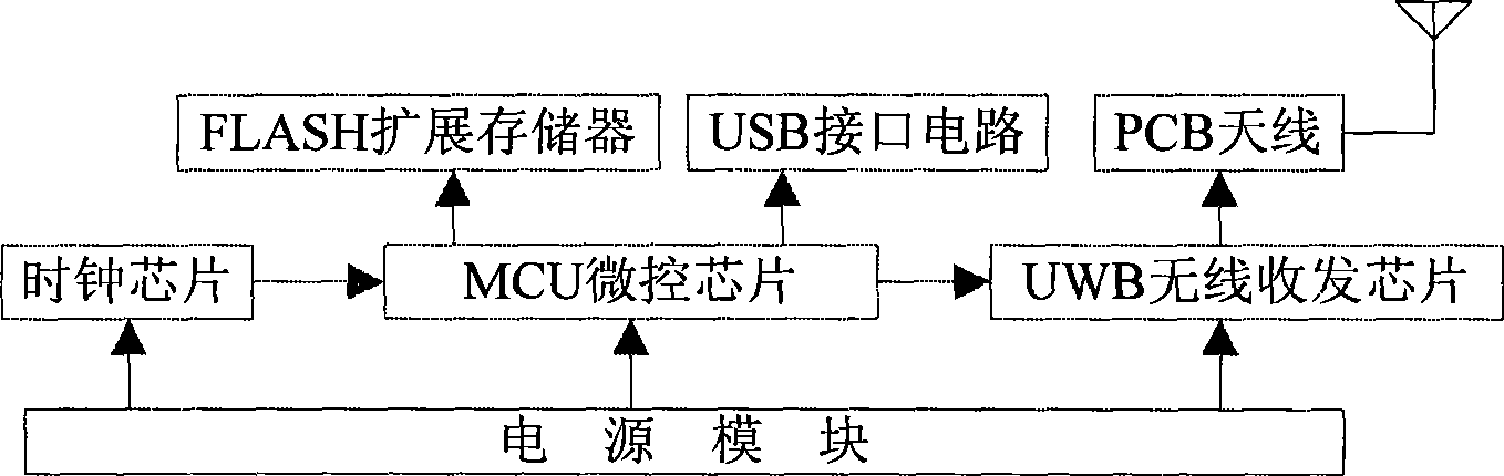
[0017] The stress wireless sensor node is composed of strain gauge, signal conditioning circuit, MCU micro-control chip, UWB wireless transceiver chip, FLASH expansion memory, USB interface circuit, PCB antenna, clock chip and power module, and the strain gauge is connected to the signal conditioning circuit , the output end of the MCU micro-control chip is connected to the UWB wireless transceiver chip, FLASH expansion memory and USB interface ...


PUM


Abstract

The invention discloses a method for detecting stress field of a hoist drum and a device thereof, and belongs to the detection methods and detection devices of drum stress field. In the device, a damper brake holder is positioned at the outside of the hoist drum, a wireless stress sensor node is fixed on the hoist drum, an anchor node is fixed on the damper brake holder, a sink node is fixed on the housing of a hoist operating console, and the sink node is connected with an industrial computer by a USB interface. The detection method and the device have the advantages of no any potential safety hazard to a hoisting system, being safe and reliable; very high communication rate and communication reliability and quick response speed to the system due to the use of UWB wireless communication technology; good operation conditions and convenient mounting and maintenance of the sensor node; low power consumption design of the wireless sensor node by which two AA batteries can be used for one year and which solves the power supply problem; and a self-diagnostic function of the sensor node, which facilitate to inform maintenance personnel to replace the sensor node or the batteries in time when the sensor node is damaged or the batteries run down.

Description

technical field [0001] The invention relates to a method and a device for detecting the stress field of a roller, in particular to a method and a device for detecting the stress field of a hoist roller. Background technique [0002] At present, the monitoring of the operating state of the hoist is realized through the detection of the tension of the hoisting wire rope. The detection methods of lifting wire rope tension include direct detection method and indirect detection method. The direct detection method is to install a wire rope tension detection device on the top of the lifting container, which is composed of a sensor, a signal acquisition module, a wireless transmission module and a storage battery. The detected steel wire rope tension signal is sent by the wireless transmitting module, and is received by the receiving module at the wellhead for data processing to obtain the wire rope tension. There are three main types of sensors for detecting wire rope tension: te...

Claims


Application Information

Patent Timeline
Patent Type & Authority Applications(China)
IPC IPC(8): G01L1/00H04B1/69H04B1/7163H04W84/18
CPCY02D30/70
Inventor 朱真才邵杏国周公博陈光柱訾斌陈义强鲍久圣韩振铎
Owner CHINA UNIV OF MINING & TECH
Why Eureka
Try Eureka