Dark field illumination objective lens apparatus
A technology for illuminating objective lenses and illuminating devices, applied in microscopes, optics, instruments, etc., can solve problems such as the change of the focal length of the light source without consideration, and achieve the effect of improving inspection capabilities and improving work efficiency
- Summary
- Abstract
- Description
- Claims
- Application Information
AI Technical Summary
Problems solved by technology
Method used
Image
Examples
Embodiment approach 1
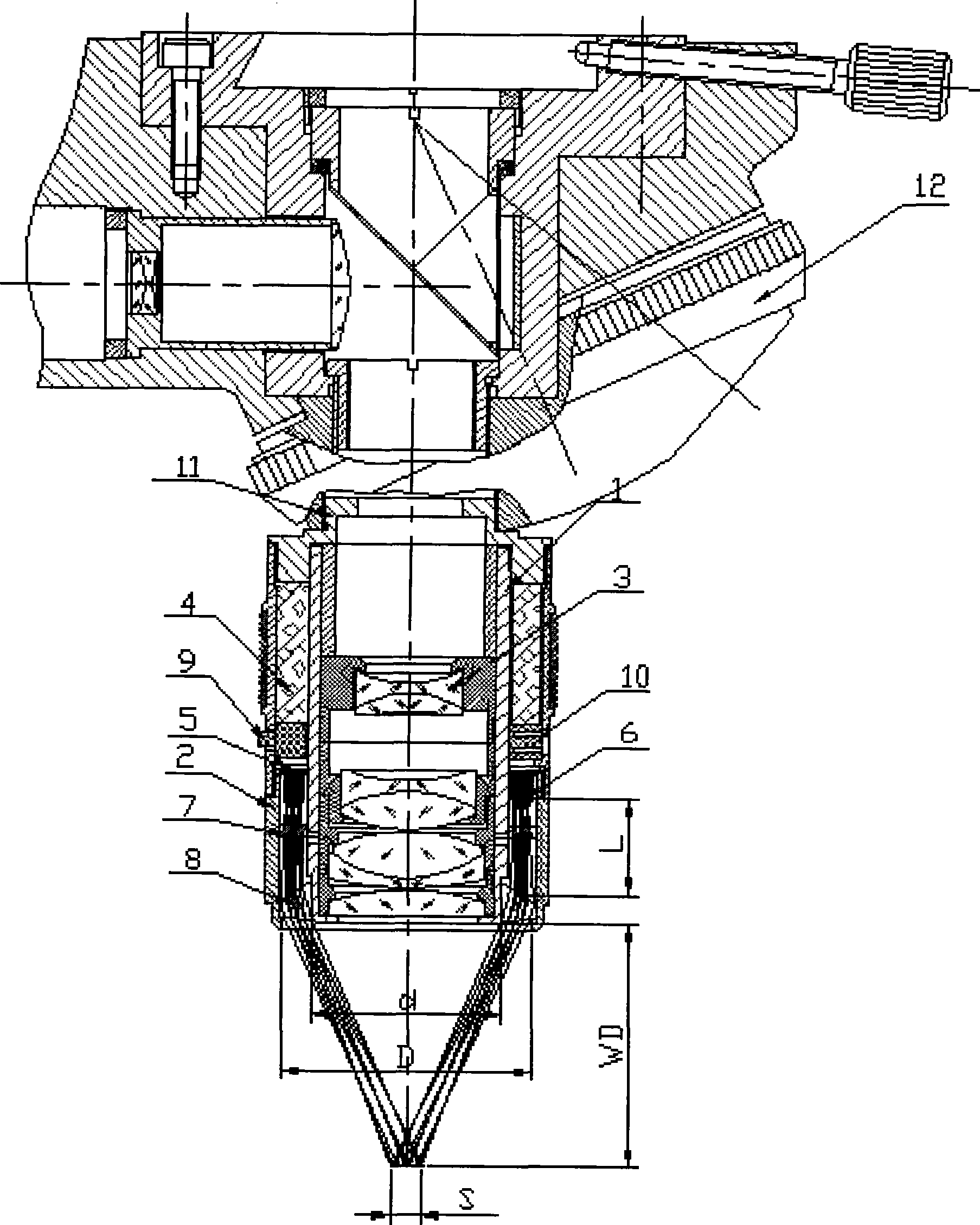
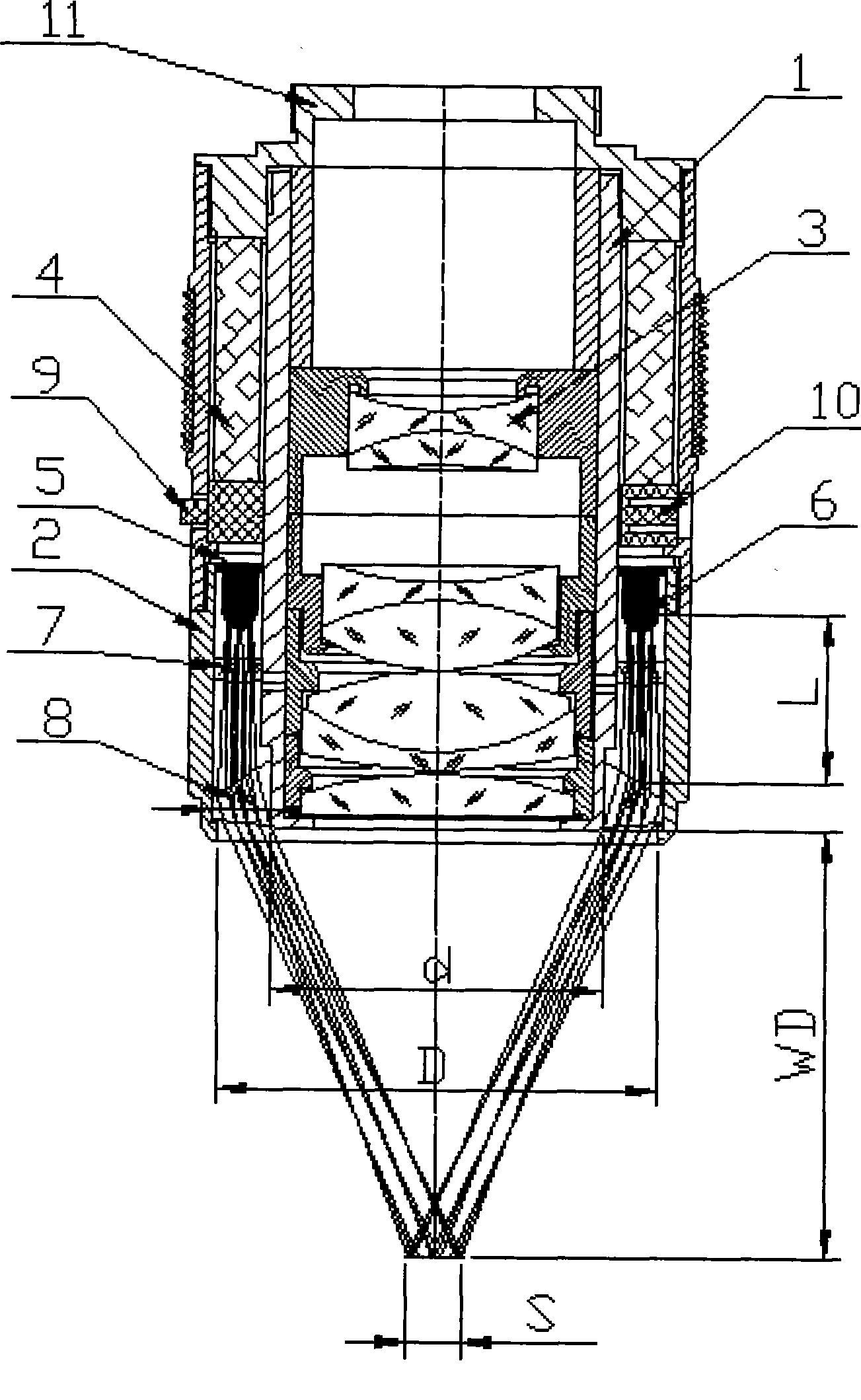
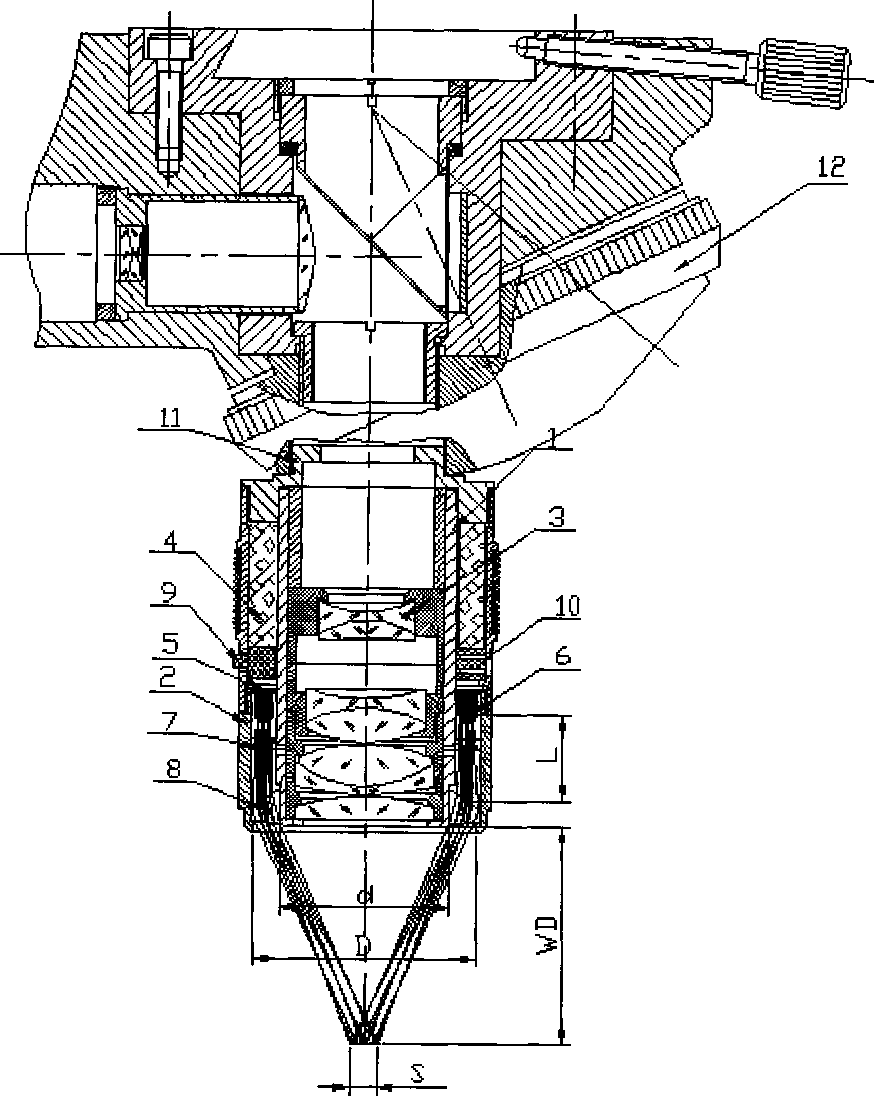
[0036] FIG. 1 is a cross-sectional view showing a dark field illumination objective lens device according to Embodiment 1 of the present invention.
[0037] This embodiment is composed of an inner cylinder 1 and an outer cylinder 2 whose axes coincide. A lens group 3 for imaging is installed in the inner cylinder 1. The outer diameter of the inner cylinder 1 facing the object to be observed is d (the inner diameter of the ring), which is equivalent to the outer diameter of the bright field lens when the objective lens is used for observation in the bright field. The axis of the outer cylinder 2 is the same as that of the inner cylinder 1. There is an annular space between the outer tube 2 and the inner tube 1. From top to bottom in the annular space are the annular battery 4, the substrate 5 on which the LED element is mounted, the LED element 6, and the compensation lens 7 to improve the parallelism of the LED emitted light, which converts the illumination light emitted by the...
Embodiment approach 2
[0046] Refer to the dark field illumination objective lens device using an aspherical mirror 13 shown in FIG. 3. Except for the spherical mirror 13, the rest of the structure is the same as the first embodiment, so the description of the parts other than the aspheric mirror is omitted here.
[0047] In the second embodiment, similar to the first embodiment, the illumination area S satisfies S≤(Dd), where D and d are the inner diameter of the outer cylinder and the outer diameter of the inner cylinder (the outer diameter of the inner cylinder holding the imaging lens group) ). In addition, the distance L between the LED element 6 and the aspheric mirror 13 preferably satisfies L> 3.3(D-d).
[0048] The aspheric mirror 13 forms a tire surface, and converts incident light into parallel light in the meridian plane. Therefore, the aspherical mirror 13 converts the illuminating light emitted by the LED elements arranged in a ring into parallel light in the sub-object plane, and irradia...
Embodiment approach 3
[0050] Hereinafter, with reference to FIG. 4, an embodiment in which the illuminating light emitted by the LED element is obliquely irradiated onto the illuminating area S using a ring-shaped tire surface lens to realize an objective lens device for dark field observation will be described in detail.
[0051] 4 is a cross-sectional view of a dark-field illumination objective lens device with a tire rim lens 14 installed at the front end of an outer cylinder. In the third embodiment, the LED mounting method is different from the first and second embodiments. In order to make the light emitted by the LED element directly obliquely irradiate the illumination area S without turning the optical axis, the tip of the outer tube 2 accommodating the LED element With respect to the inner cylinder 1, the part is in a conical shape that is opened. That is, the outer tube 2 extends from the middle of the inner tube 1 to the front end in an umbrella shape, and is used for mounting and fixing t...
PUM
 Abstract
Description
Claims
Application Information
 - R&D
- Intellectual Property
- Life Sciences
- Materials
- Tech Scout
- Unparalleled Data Quality
- Higher Quality Content
- 60% Fewer Hallucinations
Browse by: Latest US Patents, China's latest patents, Technical Efficacy Thesaurus, Application Domain, Technology Topic, Popular Technical Reports.
© 2025 PatSnap. All rights reserved.Legal|Privacy policy|Modern Slavery Act Transparency Statement|Sitemap|About US| Contact US: help@patsnap.com


