
In-mold moulding touch control module group and producing method thereof

A touch module and in-mold molding technology, applied in optics, instruments, optomechanical equipment, etc., can solve problems such as accumulation of dust, increased step thickness, complicated manufacturing process, etc., to reduce man-hour cost, improve efficiency, simplify The effect of the production process

Active Publication Date: 2009-04-22
TRENDON TOUCH TECHNOLOGY CORPORATION
View PDF1 Cites 8 Cited by
  • Summary
  • Abstract
  • Description
  • Claims
  • Application Information

AI Technical Summary

Problems solved by technology

[0005] However, the capacitive touch panel must be combined with a housing for loading the touch panel in the production process to become a touch panel for electronic products; as disclosed in Taiwan's new patent No.M274735 The display panel assembly structure is the current technology in the industry, but it is still manufactured by lamination and lamination, including the above-mentioned touch panel or its prefabricated display panel, which is attached to the pre-molded housing assembly groove However, the manufacturing process is complicated, wastes man-hours, increases the step-like thickness formed by lamination, uses for a period of time, and is easy to accumulate dirt on the step surface or gaps, etc.

Method used


Image

  • In-mold moulding touch control module group and producing method thereof
  • In-mold moulding touch control module group and producing method thereof
  • In-mold moulding touch control module group and producing method thereof

Examples


Embodiment Construction

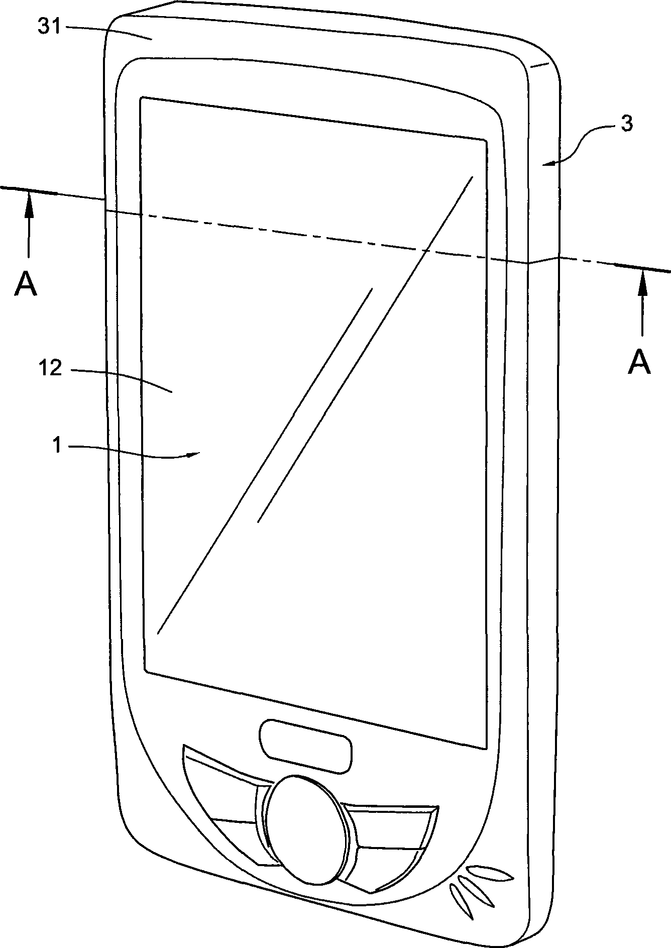
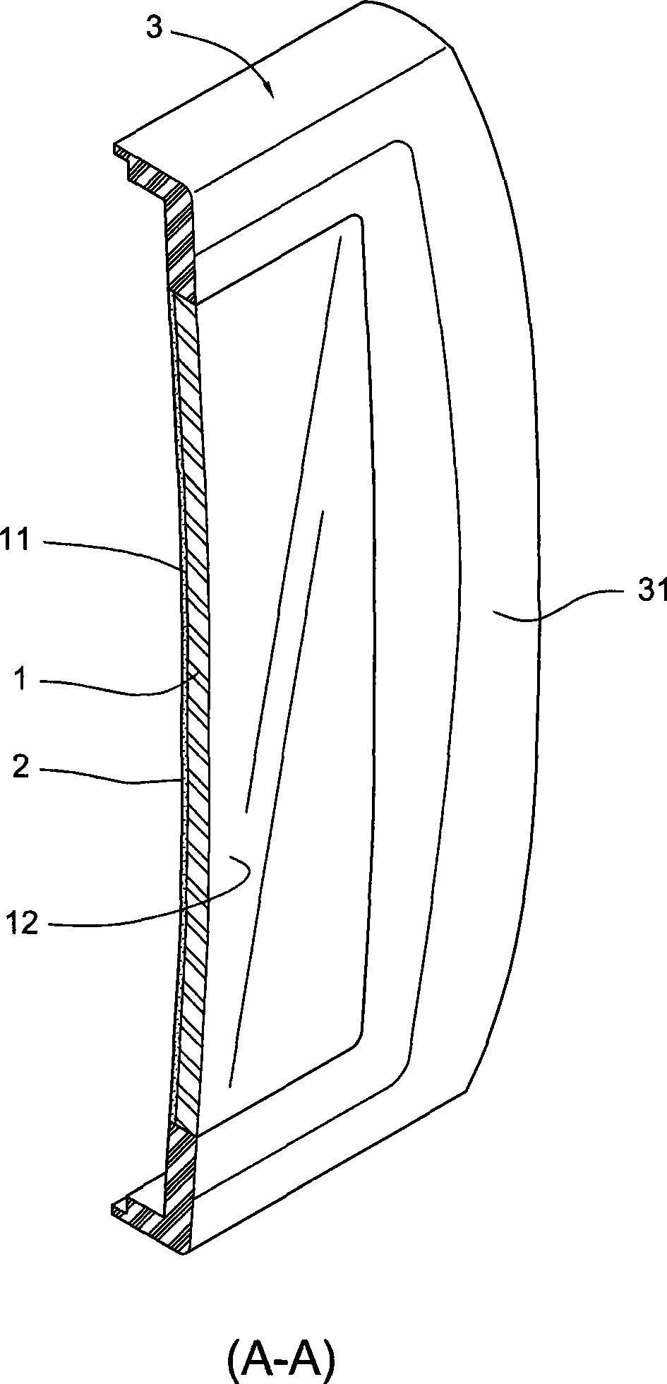
[0027] In the following, the structural composition and the effects that can be produced of the in-mold forming touch module and its production method of the present invention are described in detail as follows with preferred embodiments in conjunction with the accompanying drawings:

[0028] figure 1 It is a three-dimensional view of an electronic product housing with a touch module, figure 2 for figure 1 Three-dimensional cross-sectional view of the components. Depend on figure 1 with figure 2 It can be seen that the in-mold forming touch module of the present invention includes:

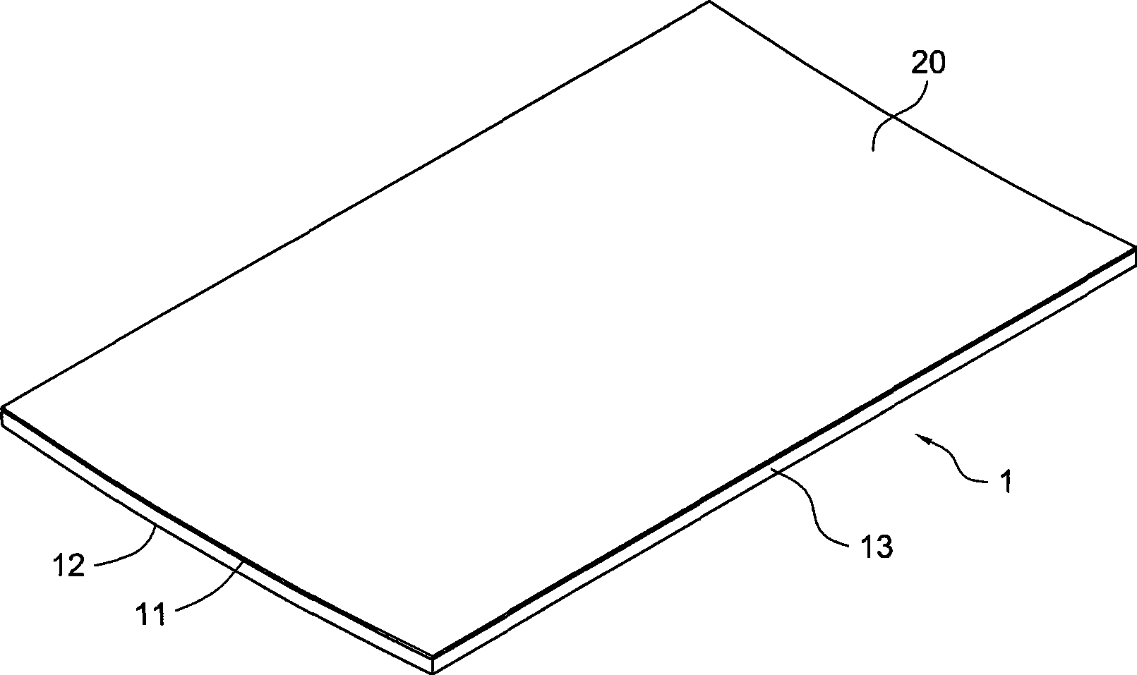
[0029] A see-through conductive carrier 1 has an inner surface 11 and an outer surface 12 (with Figure 8 As shown), there is a capacitive electrode layer 2 on the inner surface 11 (with Figure 4 shown), is a touch sensing circuit 21 made of indium tin oxide, and the outer surface 12 can be used to touch the sensing circuit 21;

[0030] A molded shell 3 is integrally covered and bonded t...


PUM


Abstract

The invention discloses an in-mold forming touch control module comprising a perspective conductive carrier board and a molded shell body, a capacitive electrode layer which is a touch control sensing circuit made from indium tin oxide is arranged on one inner surface of the carrier board, the sensing circuit can be touched by one outer surface of the carrier board, and the shell body is coated and combined at the peripheral edges of the carrier board. The invention also comprises a production method of the in-mold forming touch control module, comprising the steps: the indium tin oxide is coated on the inner surface of the carrier board, the sensing circuit is formed by processing; the carrier board is arranged in a mold cavity, and molding material is injected in the mold cavity to form the molded shell body which is integratedly coated and combined at the peripheral edges of the carrier board, thereby improving the touch control sensitivity of the module and simplifying the process. The in-mold forming touch control module and the production method are conductive to the simple implementation in the environment of an injection molding machine which is provided with automatic loading and unloading devices and further conductive to enhancing the effectiveness of automatic production, compared with the prior art which adopts the layer iteration adhesion mode, the production method can effectively simplify the production process and reduce the working time and the cost.

Description

technical field [0001] The invention relates to an in-mold forming touch module and a production method thereof, in particular to a module technology for covering and combining a touch panel with a sensing circuit by using an in-mold injection molding technology. Background technique [0002] In Mold Touch (In Mold Touch) is derived from a combination of in-mold injection molding technology and touch panel manufacturing technology. [0003] Among them, in-mold injection molding technology has been widely used in the molding and processing of some plastic products in the factory. It must use a mold to inject molten plastic into the mold cavity with the contour shape of the object to be formed. , to make the shaped object. It is known that the more advanced in-mold technology now includes an In Mold Label (IML) technology, which can first implant a material to be bonded into the mold cavity, and then put the molten plastic Inject into the mold cavity, cover and combine the m...

Claims


Application Information

Patent Timeline
IPC IPC(8): G06F3/044B29C45/14G03F7/00
Inventor 李旻益苏圣镔
Owner TRENDON TOUCH TECHNOLOGY CORPORATION
Learn More