Upper part of an assembled piston

A technology of parts and pistons, which is applied in the field of upper parts of assembled pistons, can solve problems such as high cost

Active Publication Date: 2009-04-22
MAHLE INT GMBH
View PDF1 Cites 0 Cited by
  • Summary
  • Abstract
  • Description
  • Claims
  • Application Information

AI Technical Summary

Problems solved by technology

The downside is that both the materials for the layers and the cost of this detonation spraying process are very expensive

Method used


Image

  • Upper part of an assembled piston
  • Upper part of an assembled piston

Examples


Embodiment Construction

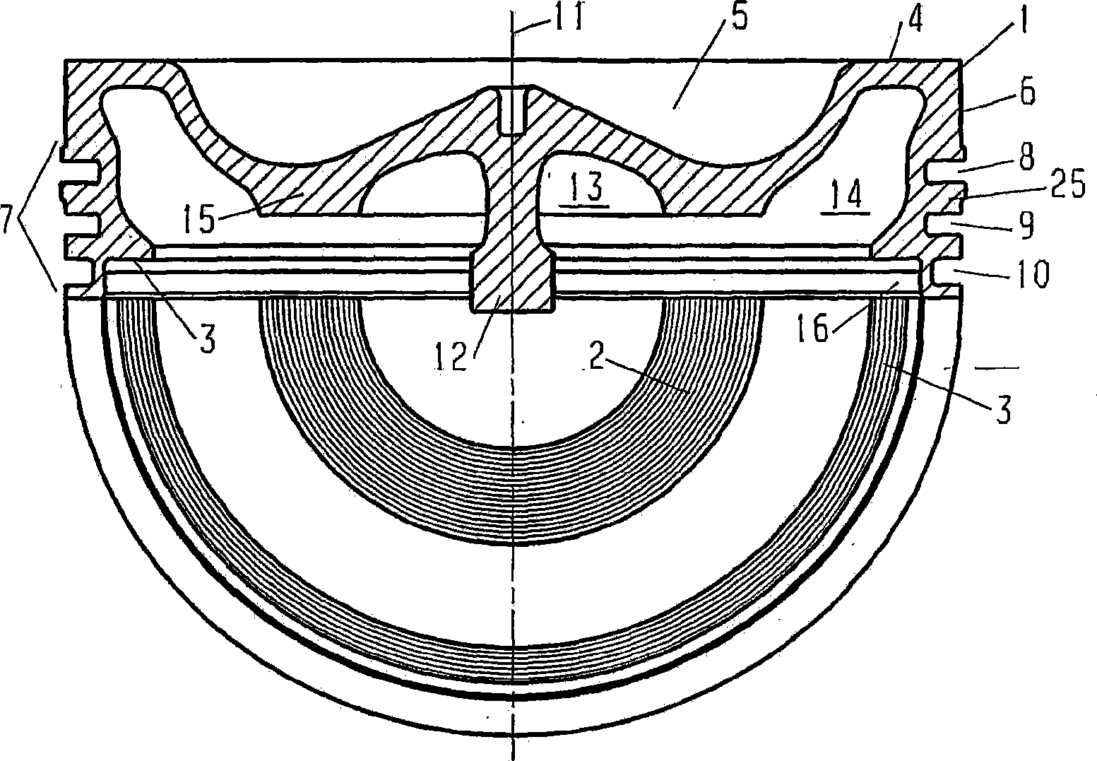
[0008] figure 1 The upper part 1 of the piston is shown, the lower part of which is not shown in the schematic diagram, in figure 1 A bottom side view of half of the upper part 1 is briefly shown in , which shows the inner radial contact surface 2 and the outer radial contact surface 3 , wherein the upper part bears against the piston 1 via the contact surfaces 2 and 3 on the lower part. The upper part 1 is produced from steel. The lower part can be made of steel, aluminum or cast iron with nodular graphite.

[0009] The upper part 1 has a piston crown pocket 5 formed in its piston crown 4 . The radially outer region of the upper part 1 on the piston top side is designed as a refractory blunt 6 to which a piston ring 7 with three annular grooves 8 , 9 , 10 is connected in the direction away from the piston top.

[0010] The underside of the upper part 1 facing away from the piston crown has a screw 12 coaxial to the piston axis 11 , by means of which the upper part 1 is sc...


PUM


Abstract

An upper part (1) of an assembled piston is disclosed, comprising a radially directed inner contact surface (2) arranged on the underside of an annular rib (15) and a radially directed outer contact surface (3) arranged on the underside of an annular wall (25), the outer (3) and the inner contact surface (2) each having a grooved profile in the form of concentric grooves with an average depth between Rz 10 and Rz 30. The wear on the contacting surfaces of the upper piece and the lower piece of the assembled piston is thus reduced.

Description

technical field [0001] The invention relates to an upper part of an assembled piston according to the preamble of claim 1 . Background technique [0002] In the patent application document DE 36 33 134 C2, an assembled piston consisting of an upper part and a lower part is disclosed, in which piston, in order to reduce the wear of the surfaces of the upper part and the lower part which come into contact with each other, between the two A high wear-resistant layer is arranged between the faces. The layer is applied on one of the two contact surfaces according to the detonation spraying process to ensure good adhesion of the layer to the contact surfaces. This layer can be formed from a tungsten carbide-cobalt alloy or from a copper-nickel-indium alloy. A disadvantage of this is that both the material of the formed layer and the cost of this detonation spraying process are very expensive. Contents of the invention [0003] The object of the invention is to avoid this disa...

Claims


Application Information

Patent Timeline
Patent Type & Authority Applications(China)
IPC IPC(8): F02F3/00
CPCF02F3/0023F16J1/09F02F3/00
Inventor 迪特尔·梅斯默克里斯托夫·盖斯勒罗兰德·施密特
Owner MAHLE INT GMBH
Why Eureka
Try Eureka