Optical modulator

A technology of optical modulators and modulators, applied in optics, instruments, optical components, etc., can solve problems such as inability to reset separate reflectors

Inactive Publication Date: 2009-04-22
QINETIQ LTD
View PDF5 Cites 10 Cited by
  • Summary
  • Abstract
  • Description
  • Claims
  • Application Information

AI Technical Summary

Problems solved by technology

Therefore, the drive electrodes in EP 1 341 025 do not form part of the optical structure of the device
Finally, the addressing strategy discussed in EP 1 341 025 does not reset discrete reflectors within the display system

Method used


Image

  • Optical modulator
  • Optical modulator
  • Optical modulator

Examples


Embodiment Construction

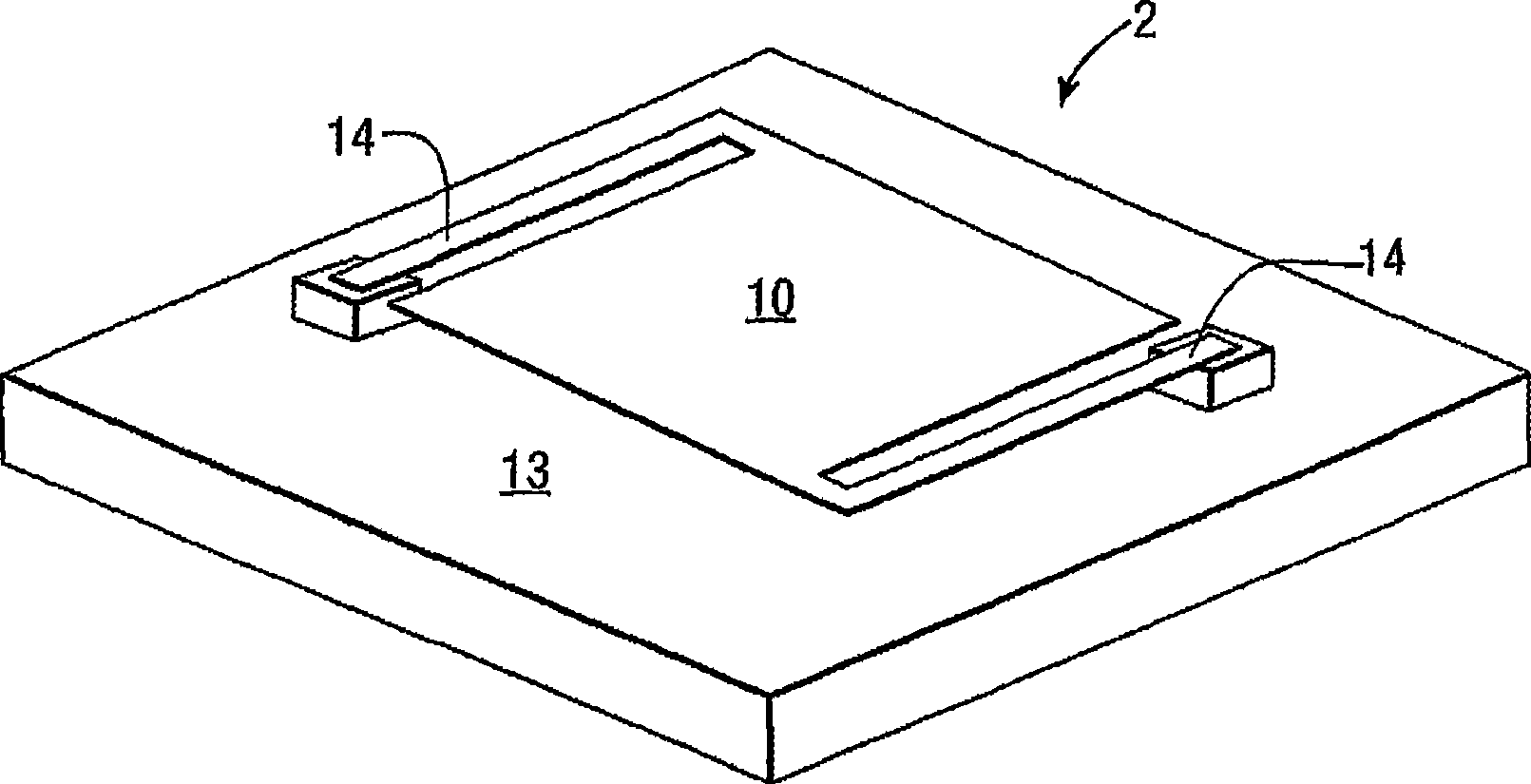
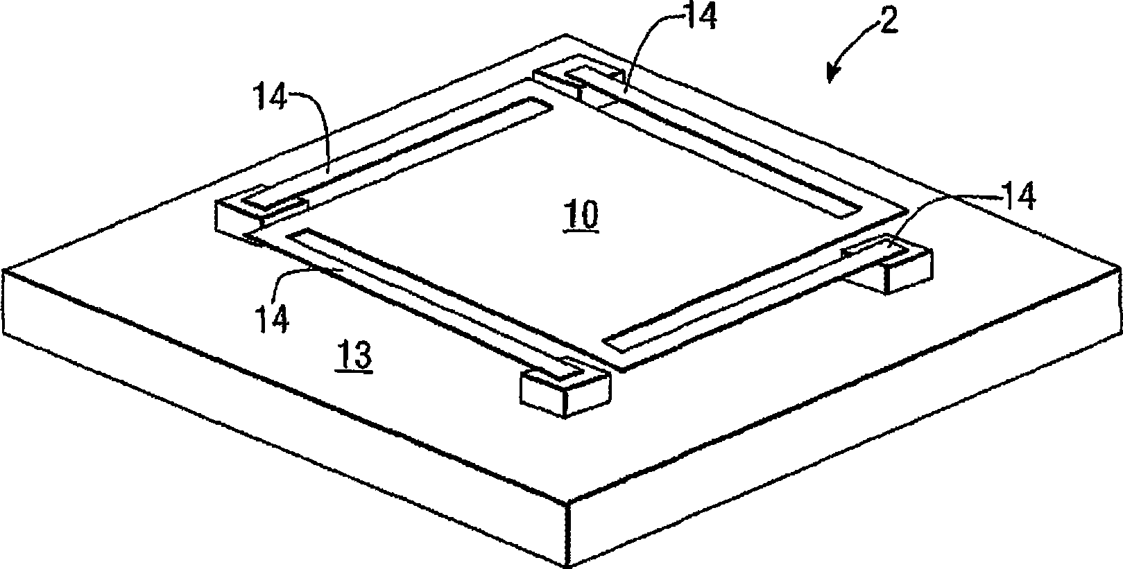
[0070]Referring now to the drawings, in which like reference numerals identify corresponding or similar elements in the various views, Figure 1 shows a large area MOEMS optical modulator as described in the applicant's co-pending UK patent application GB 0521251 , the content of which is hereby incorporated by reference.

[0071] As a brief illustration, the modulators described in GB 0521251 utilize optical interference effects to control the intensity and / or phase of light beams and are based on a single MOEMS optical modulator or an array of MOEMS optical modulators in which one or more movable micromirrors are Suspended above the substrate. This device can be used for transmission of multiple wavelengths where the substrate (eg silicon) is optically transmissive, and can be used for reflection for a substantially larger range of wavelengths.

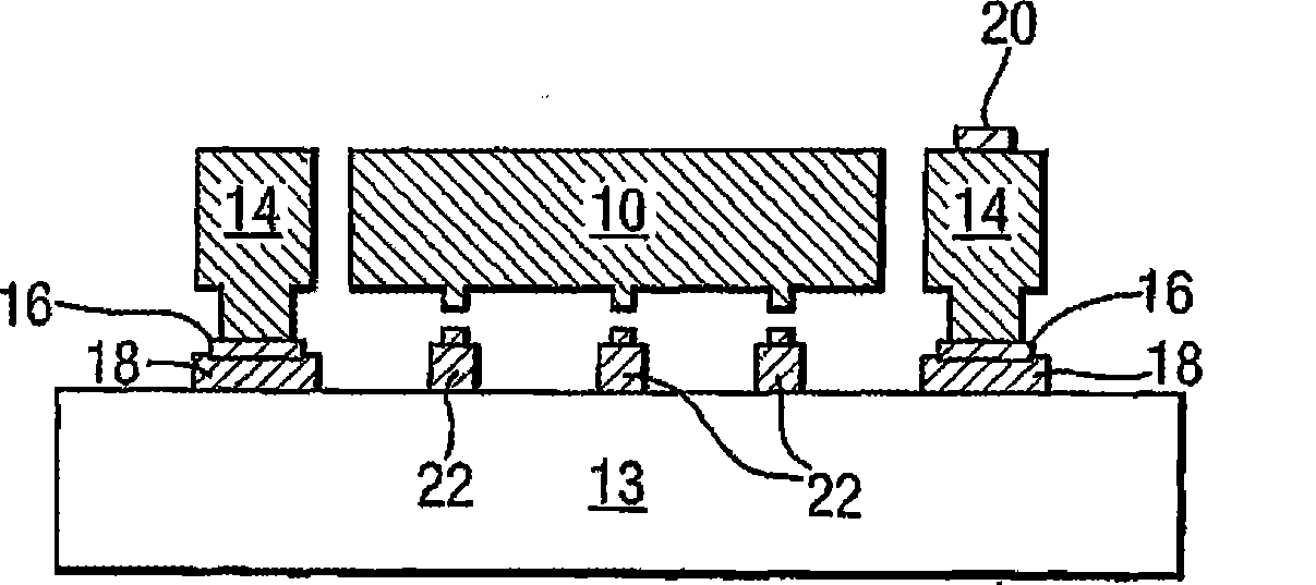
[0072] A single light modulator 2 comprises a movable suspension layer 10 , hereinafter referred to as a micromirror 10 suspended ...


PUM


Abstract

The invention relates to an optical modulator. A micro-opto-electro-mechanical systems (MOEMS) electro optical modulator (2) having an electrically tuneable optical resonator comprises an asymmetric Fabry-Perot etalon incorporating a mirror (10) resiliency biased with respect to a substrate (13) and moveable in relation thereto in response to a voltage applied there-between. The optical modulator (2) is capable of modulating electromagnetic radiation having a plurality of wavelengths. The modulator is adapted to modulate the transmission of short wave infrared radiation (SWIR), medium wave infrared radiation (MWIR) and long wave infrared radiation (LWIR) and the reflection of visible radiation. A spatial optical modulator having a plurality of said MOEMS optical modulators (2). A method of addressing said spatial optical modulator.

Description

technical field [0001] The invention relates to an optical modulator and its control method. The present invention relates in particular, but not exclusively, to micro-opto-electromechanical systems (MOEMS) spatial light modulators for use in imaging systems. Background technique [0002] Spatial light modulators are valuable for a variety of imaging applications, including scientific instruments and commercial products. [0003] By way of tracing the background of the present invention, MOEMS light modulators are known which utilize light interference effects to control the intensity and / or phase of a light beam. For example, Lewis et al., SP1E-5614 (1994), pp. 24-30, describe an optical modulator structure based on a MOEMS device with an adjustable gap that acts as an optical resonant cavity ( silicon-air-silicon Fabry-Perot standard). However the device described in the Lewis et al. article differs from most MOEMS light modulator structures in that it can function in t...

Claims


Application Information

Patent Timeline
Patent Type & Authority Applications(China)
IPC IPC(8): G02B5/28G02B26/00
CPCG02B5/284G02B5/281G02B26/001G02B26/0833G02F1/21G02F2201/14
Inventor M·E·麦尼K·L·路易斯A·M·斯科特C·W·斯林格尔K·M·布伦森G·W·史密斯
Owner QINETIQ LTD
Why Eureka
Try Eureka