Gas floatation separation device

A technology of air flotation separation and separation area, which is applied in the direction of solid separation, liquid separation, separation methods, etc. It can solve problems such as affecting production efficiency, complicated maintenance operations, and clogging of releasers, and achieves complete oil-water separation, high separation efficiency, and low cost. economic effect

Inactive Publication Date: 2009-04-29
宁波威瑞泰默赛多相流仪器设备有限公司
View PDF0 Cites 14 Cited by
  • Summary
  • Abstract
  • Description
  • Claims
  • Application Information

AI Technical Summary

Problems solved by technology

All kinds of releasers are installed inside the air flotation separation device. Because the releaser will often be blocked, an external energy cleaning system needs to be added. Sometimes the entire air flotation separation device needs to be stopped and the releaser can only be repaired after it is emptied. The maintenance operation is complicated. Trouble, but also affect production efficiency

Method used


Image

  • Gas floatation separation device
  • Gas floatation separation device
  • Gas floatation separation device

Examples


Embodiment Construction

[0029] The present invention will be further described in detail below in conjunction with the embodiments of the drawings.

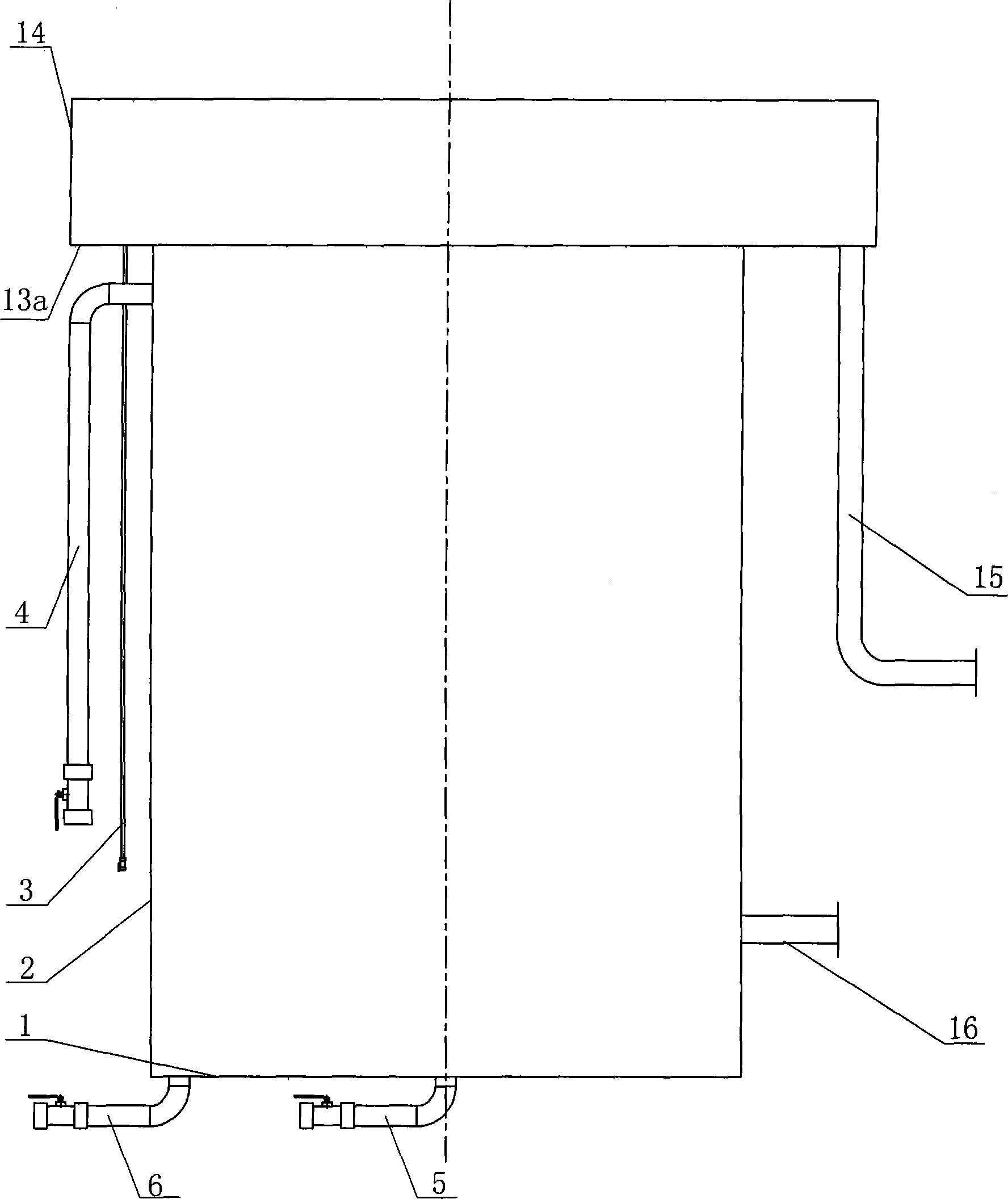
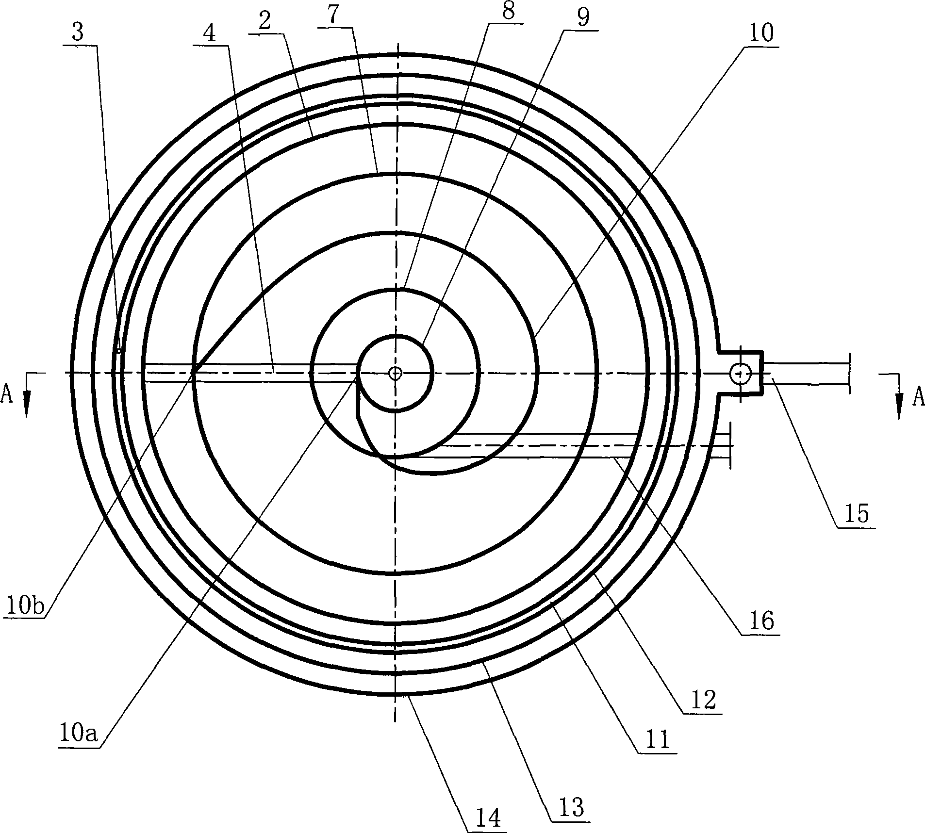
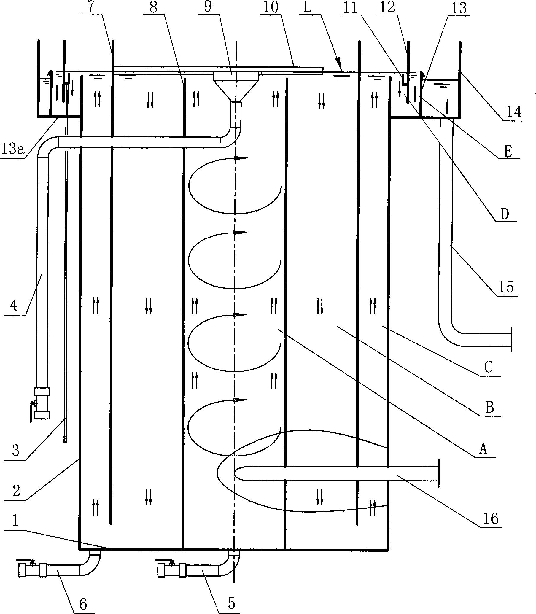
[0030] Such as Figure 1 ~ Figure 3 As shown, the air flotation separation device includes an outer cylinder 2, a swirling mixing cylinder 8 arranged in the center of the outer cylinder 2, and a first slag stopper 7 arranged between the outer cylinder 2 and the swirling mixing cylinder 8. , The three have the same centerline;

[0031] Wherein, the outer cylinder body 2 and the swirling mixing cylinder 8 both have a closed bottom. In this embodiment, the bottom of the swirling mixing cylinder 8 is overlapped on the bottom 1 of the outer cylinder 2 so that the bottoms of the two are connected as a whole. There is a distance between the bottom end of the first slag blocking cylinder 7 and the bottom 1 of the outer cylinder 2 to form a water flow channel. The swirl mixing cylinder 8 and the first slag blocking cylinder 7 on the periphery thereof separate the int...


PUM


Abstract

The invention discloses an air flotation separation device, comprising an external cylinder (2), a rotational flow mixed cylinder (8), a first slag-retaining cylinder (7), a first scum drainage pipe (4) and a scum collecting guide plate (10); wherein, the bottom end of the first slag-retaining cylinder (7) and the bottom of the external cylinder (2) have spacing so as to form a water passage; the bottom of the side wall of the rotational flow mixed cylinder (8) is connected with a water inlet pipe (16) which enters in tangent direction; the periphery of the top of the external cylinder (2) is provided with a clean water collecting trench (14); and the scum collecting guide plate (10) is a strip-typed plate in an involute shape, with the involute direction right opposite to the water rotational flow direction in the rotational flow mixed area (A). Compared with the prior art, the air flotation separation device does not need to add external energy cleaning systems, achieves the object of long-term continuously and stably running, and ensures that the requirement that the micro air bubbles adhere to the dispersed oil, emulsified oil and dissolved oil of small particle size as much as possible is met, thus achieving the object of high-efficiency separation of oil from water. The air flotation separation device is especially suitable for low-consistency water containing oil.

Description

Technical field [0001] The present invention relates to the technical field of oil-water separation treatment, in particular to an air flotation separation device that uses an air flotation method to separate oil and water. Background technique [0002] The oily water in the production process of oil and natural gas comes from various links such as petroleum and natural gas extraction, processing, refining, storage and transportation. The quality of oily water is complex, including crude oil, various impurities, and additions during subsequent production and processing. Chemical agents and some microorganisms. [0003] Generally, the physical states of oil in oil-containing water can be roughly divided into five types: slick oil, dispersed oil, emulsified oil, dissolved oil and solid attached oil, usually coexisting in the above-mentioned physical states. The commonly used physical treatment methods mainly include gravity method, centrifugal method, air flotation method, filtrati...

Claims


Application Information

Patent Timeline
Patent Type & Authority Applications(China)
IPC IPC(8): B01D17/035B03D1/02
Inventor 马立峰樊燕王守波
Owner 宁波威瑞泰默赛多相流仪器设备有限公司
Why Eureka
Try Eureka