Air-bearing support workstation design method

A design method and workbench technology, applied in metal processing equipment, manufacturing tools, metal processing mechanical parts, etc., to achieve the effect of low implementation requirements, saving resources and time

Active Publication Date: 2011-05-04
HANS CNC SCI & TECH
View PDF4 Cites 0 Cited by
  • Summary
  • Abstract
  • Description
  • Claims
  • Application Information

AI Technical Summary

Problems solved by technology

The use of air feet not only reduces a lot of cost, but also solves the problems encountered by those four guide rails

Method used


Image

  • Air-bearing support workstation design method
  • Air-bearing support workstation design method
  • Air-bearing support workstation design method

Examples


Embodiment Construction

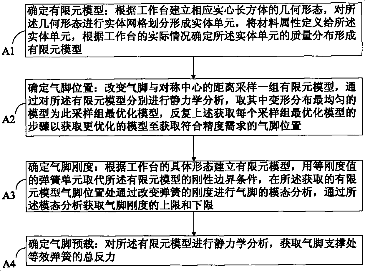
[0039] Such as figure 2 As shown, it is a flow chart of the design method of the air foot support workbench of the present invention. The method proposed by the present invention can be implemented in the entire design process of the large workbench, which not only depends on the design of the workbench but also affects the design of the workbench. Design, can be divided into two parts.

[0040] The first part is in the conceptual design stage. The internal frame structure and other details of the workbench have not yet been determined, but only the size (length, width and height), weight (total mass and concentrated mass distribution) and materials of the workbench have been initially planned. Time. At this time, it is necessary to determine the position of the guide rail slider and the air foot support before it is possible to design the specific shape inside the workbench. Relatively speaking, the position of the guide rail slider is easy to determine according to the di...


PUM


Abstract

The invention provides a design method of a gas foot support working table and includes the following steps of: A1. defining finite element models: creating a homological solid cuboid geometric shape to form the finite element models; A2. determining the location of gas feet: sampling a group of finite element models by changing the distance between the gas feet and a center of symmetry to obtain more optimized models until the positions of the gas feet meeting the precision requirements are got; A3. determining the rigidity of the gas feet: creating finite element models according to concrete forms of the working table and making modal analysis of the gas feet to obtain the rigidity of the gas feet; and A4. ascertaining the preload of the gas feet: doing statics analysis of the finite element model and obtaining the total counter force of an equivalent spring at a support point of the gas feet. The method has the advantages of being capable of ensuring that the working table reachesthe stability and mechanical properties required by the design, saving lots of resources and time consumed in measurement and specimen test, achieving the goals in the concept and design stage beforethe input of practical production, being low in implementation requirement, convenient and rapid and being able to accurately output the specific parameter conclusion of the gas feet.

Description

technical field [0001] The invention relates to a design method of a workbench, in particular to a design method of an air foot support workbench. Background technique [0002] In the large-scale industrial production of assembly line operation, the multi-axis CNC drilling machine that can improve the processing production efficiency is the trend and development trend of the CNC drilling machine today. As for the multi-axis synchronous drilling technology, basically they all face the same problem - that is, the span of the table is very long. Due to the long span, there are long overhangs on both sides of the main rail slider after positioning, where the mechanical strength is insufficient and it is easy to vibrate. At present, the widely used solutions are divided into two types: use four guide rails to replace the classic double guide rail structure, that is, add a pair of auxiliary guide rails parallel to the main guide rail under the overhanging section for support; ano...

Claims


Application Information

Patent Timeline
Patent Type & Authority Patents(China)
IPC IPC(8): B23Q1/25B23Q1/44
Inventor 高云峰叶爱鹏肖俊君李宁崔彦州宋福民雷群
Owner HANS CNC SCI & TECH
Why Eureka
Try Eureka