
Transformer and combined construction thereof

A technology of transformers and structures, applied in the direction of transformers, fixed transformers, transformer/inductor coils/windings/connections, etc., can solve the problems of poor transformer efficiency, distance from the magnetic circuit iron core, and copper sheet displacement, etc. Efficiency, area reduction, and leakage inductance reduction effects

Inactive Publication Date: 2011-04-13
ACBEL POLYTECH INC
View PDF0 Cites 0 Cited by
  • Summary
  • Abstract
  • Description
  • Claims
  • Application Information

AI Technical Summary

Problems solved by technology

[0005]2. In terms of characteristics: the several pieces of copper sheets 80 provided on the wire frame 70 were originally independent, but when soldered to the circuit board 90, Utilize the circuit on the circuit board 90 to be connected into a continuous shape, so that the current I flows in from one end of the copper sheet 80, and must pass through the circuit on the circuit board 90 to be sent to other copper sheets 80, but because the area of ​​the copper sheet 80 in contact with the air is too large , far away from the core of the magnetic circuit, which will cause a large leakage inductance, which will make the efficiency of the transformer worse
[0006] From the above, it can be seen that the existing transformer uses copper sheets to replace the primary or secondary side windings, and does not provide fixing measures for the copper sheets, which is easy to cause The displacement of the copper sheets affects the welding operation; in addition, because the copper sheets are connected to each other through the lines on the circuit board, the area in contact with the air is too large, resulting in leakage inductance, which affects the efficiency of the transformer

Method used


Image

  • Transformer and combined construction thereof
  • Transformer and combined construction thereof
  • Transformer and combined construction thereof

Examples


Embodiment Construction

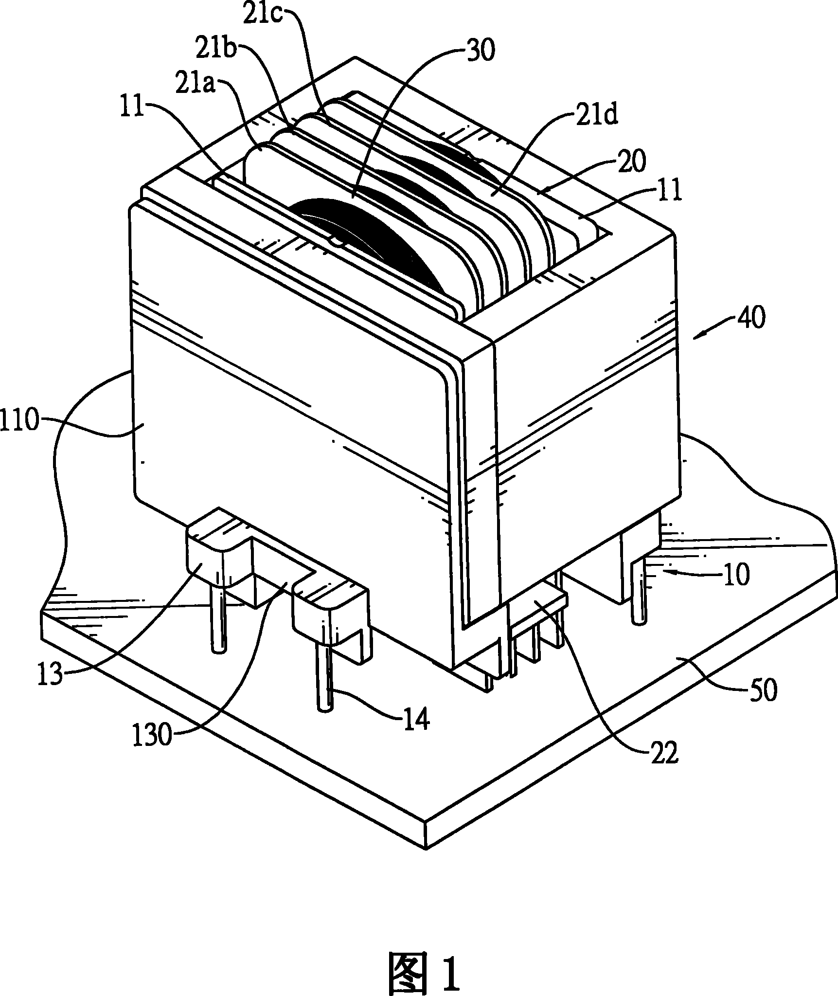
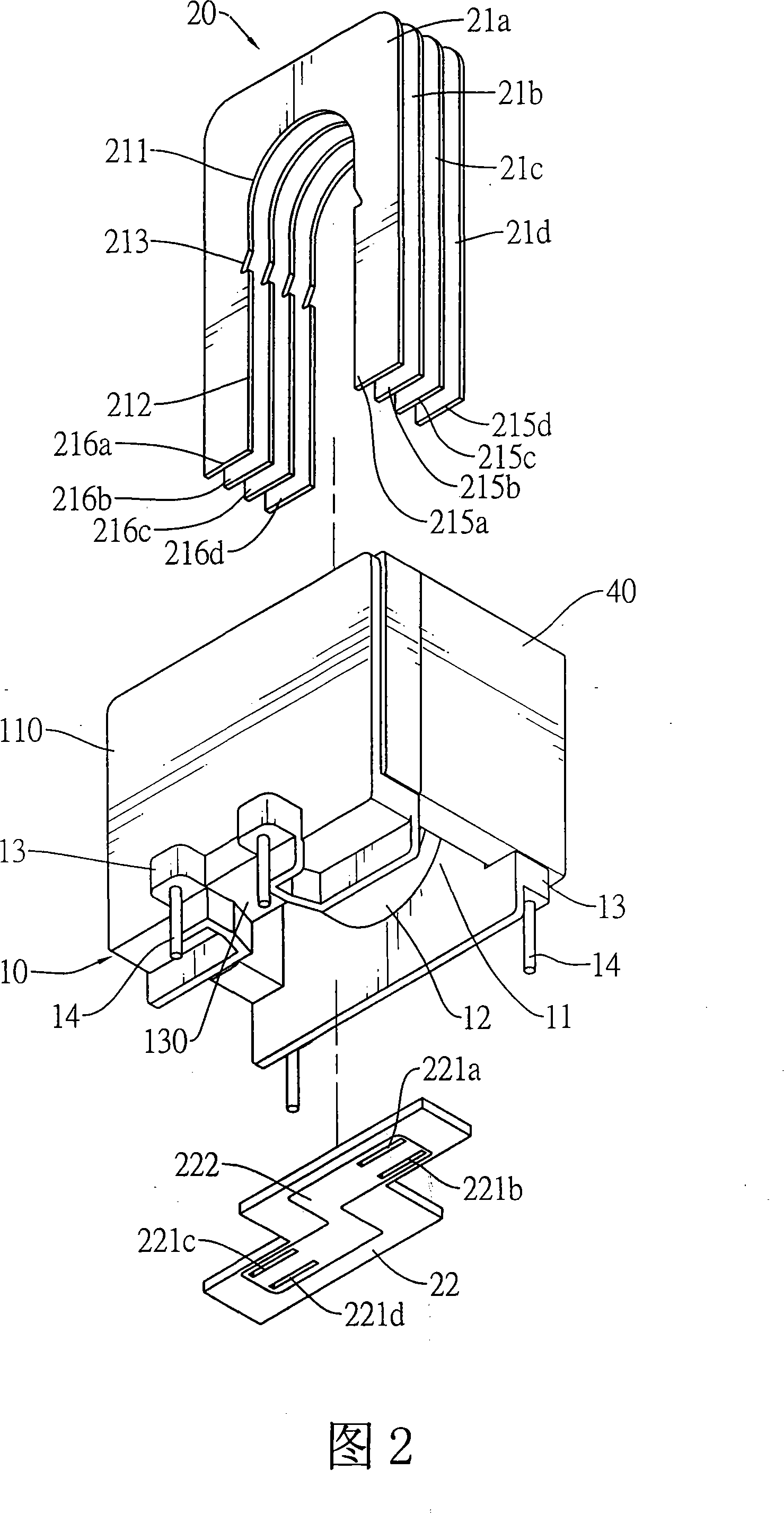
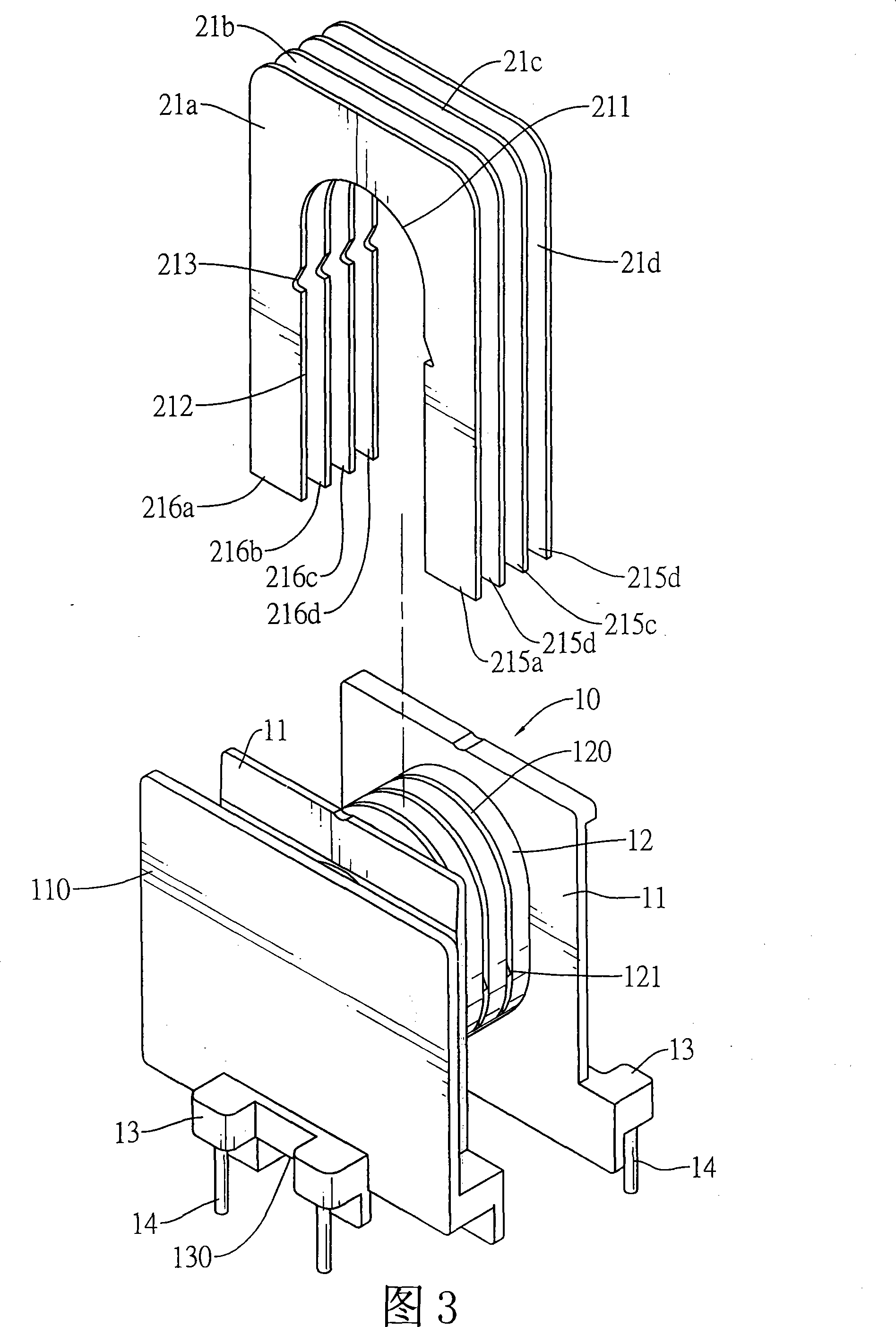
[0053]Regarding a preferred embodiment of the present invention, please refer to Fig. 1 and shown in Fig. 2 at first, mainly be to be provided with a copper sheet winding 20, a coil winding 30 and an iron core 40 on a horizontal wire stand 10; The sheet winding 20 can be used as the primary side or the secondary side, which means that when the copper sheet winding 20 is used as the primary side winding, the coil winding 30 is used as the secondary side winding; otherwise, the copper sheet winding 20 is used as the secondary side winding, and the coil winding 30 That is, the primary side winding; in addition, the present invention can be implemented in step-down transformers and step-up transformers respectively.

[0054] Please also refer to FIG. 3 , the wire frame 10 mainly forms a hollow winding part 12 in the horizontal direction between two opposite vertical side parts 11, and the bottom ends of the two vertical side parts 11 are respectively formed with pin seats 13 , The...


PUM


Abstract

The invention discloses a transformer and a combination structure thereof. A hollow winding part is formed on a horizontal wire frame for setting a primary side winding, a secondary side winding and an iron core, and the like; wherein, the primary side winding or the secondary side winding consists of U-shaped copper ring sheets; the winding part of the wire frame is formed with a plurality of caulking grooves which are matched with the shapes of the copper ring sheets and used for the copper ring sheets to be embedded; besides, a claming structure with the functions of reinforcing and combining is arranged in the caulking grooves and on the copper ring sheets, thus leading the copper ring sheets to be stably fixed on the wire frame and avoiding the displacement of the copper ring sheets caused by winding to affect a welding operation; besides, the lower side of the line frame is further provided with an electronic connection sheet so as to connect each copper ring sheet in a continuous shape, thus being capable of reducing leakage inductance and improving the working efficiency of the transformer.

Description

technical field [0001] The invention relates to a transformer and its combined structure. Background technique [0002] Transformer windings are generally composed of primary windings and secondary windings. At present, there is a transformer that uses copper sheets to replace primary windings or secondary windings, as shown in Figure 7. The schematic diagram of the frame 70 and the copper sheet 80 set on it, the wire frame 70 is roughly H-shaped, and its center is formed with a horizontal and hollow winding part 71, and the inner contour shape of several copper sheets 80 is matched with The winding portion 71 is equidistantly straddled on the winding portion 71. The copper sheets 80 are originally independent, and their two ends are respectively inserted on the circuit board 90 where the transformer is installed, and pass through the circuit board 90. The pre-laid lines (not shown in the figure) are connected to each other to form a continuous winding shape. The aforement...

Claims


Application Information

Patent Timeline
Patent Type & Authority Patents(China)
IPC IPC(8): H01F30/06H01F27/29H01F27/30H01F27/28H01F27/40
CPCH01F27/2852H01F27/2866H01F27/306H01F27/325H01F2005/043H05K1/141H05K1/18H05K3/306H05K2201/1003
Inventor 王金标
Owner ACBEL POLYTECH INC
Learn More