
Time-domain wave beam synthesizing and scanning method for open loop system ultra-wideband pulse source array

An ultra-wideband pulse and beamforming technology, applied in radio wave measurement systems, measurement devices, instruments, etc., can solve the problem of not seeing the support of pulse source array time-domain beamforming and scanning functions, and it is difficult to be widely promoted. The technical route is complex and other problems, to achieve the effect of good maintenance-free, simple structure and strong scalability

Active Publication Date: 2009-04-29
HUNAN NOVASKY ELECTRONICS TECH
View PDF0 Cites 6 Cited by
  • Summary
  • Abstract
  • Description
  • Claims
  • Application Information

AI Technical Summary

Problems solved by technology

However, its technical route is very complicated, which is not conducive to further increasing the number of array elements and realizing the beamforming output of a large-scale pulse source array, and it is poor in maintenance-free and high in design costs in practical engineering applications, so it has been difficult to obtain large-scale promotion
However, in the products and devices of other companies or individuals, there is no support for the pulse source array time-domain beamforming and scanning functions.

Method used

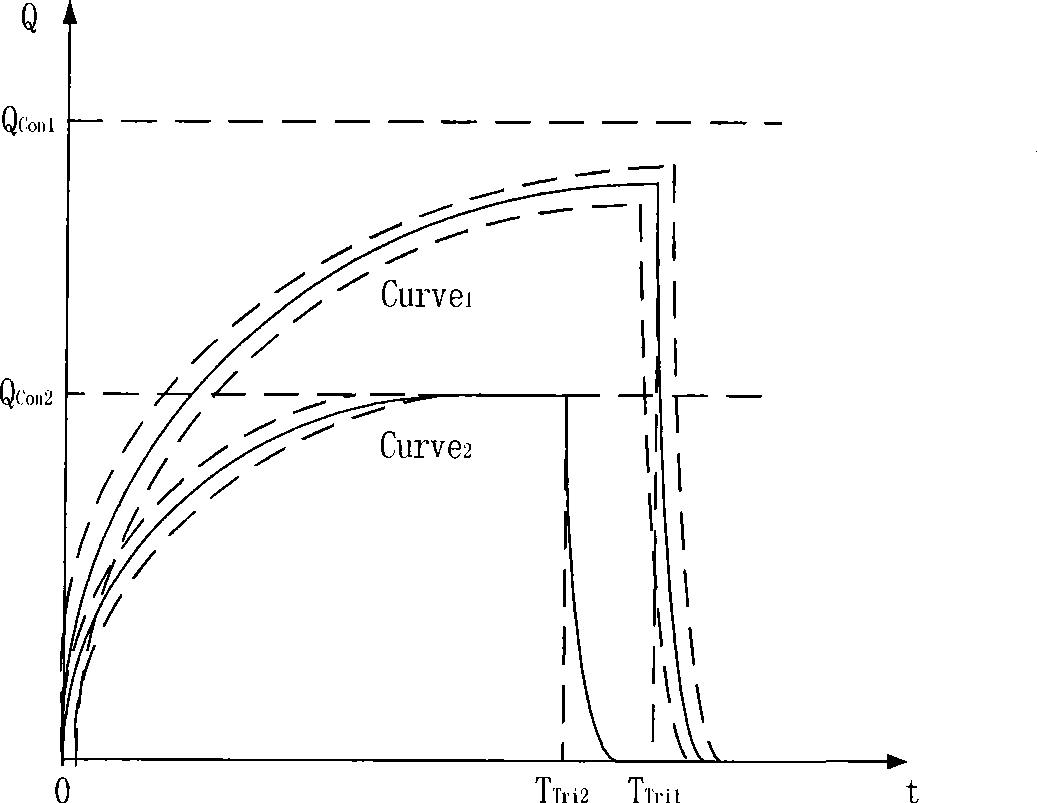
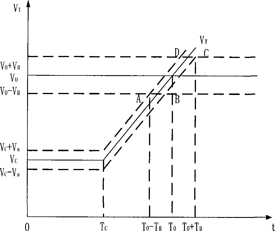

Image

  • Time-domain wave beam synthesizing and scanning method for open loop system ultra-wideband pulse source array
  • Time-domain wave beam synthesizing and scanning method for open loop system ultra-wideband pulse source array
  • Time-domain wave beam synthesizing and scanning method for open loop system ultra-wideband pulse source array

Examples


Embodiment Construction

[0035] The present invention will be described in further detail below in conjunction with the accompanying drawings and specific embodiments.

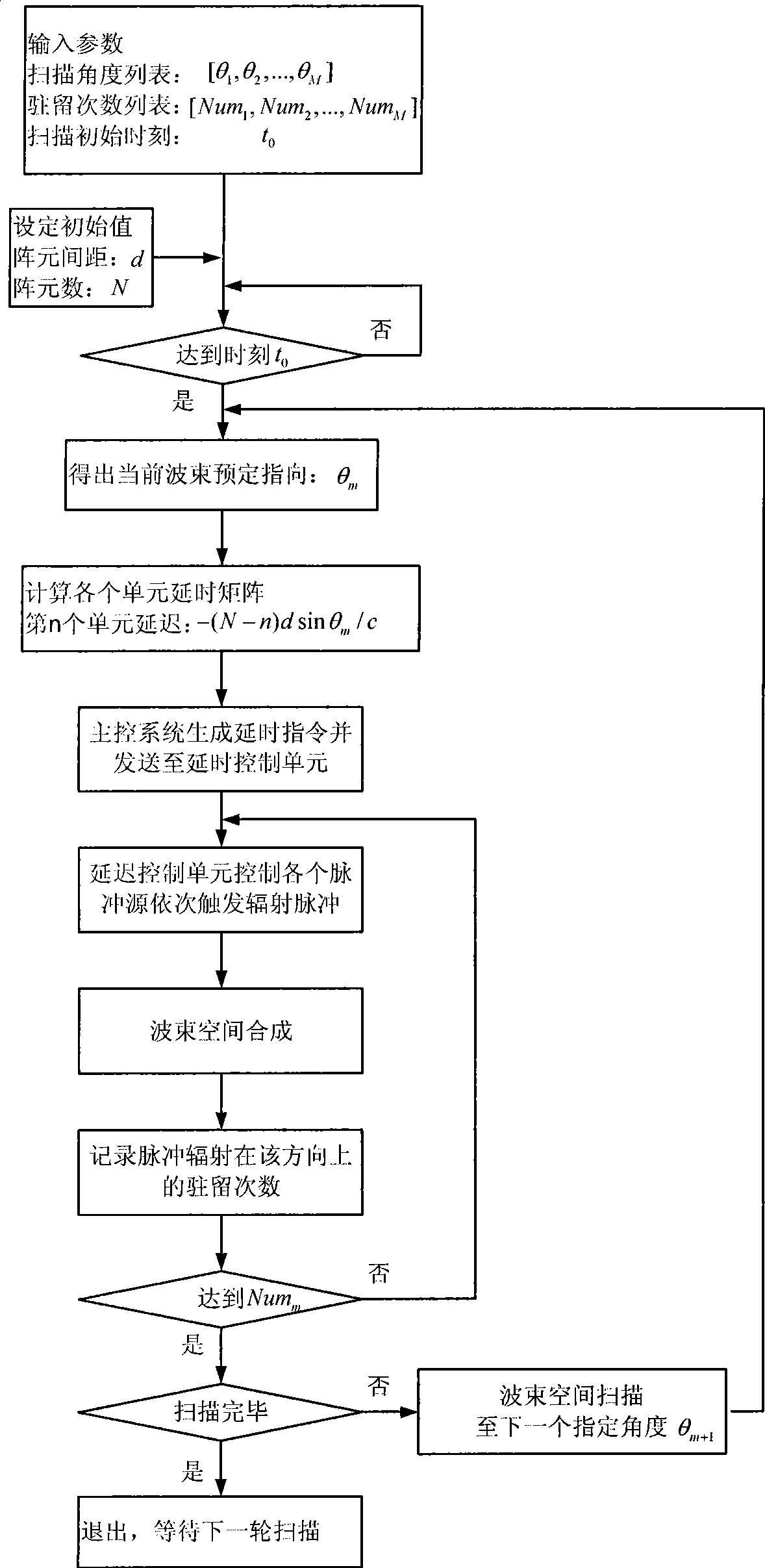
[0036]The present invention is based on an open-loop system. For a predetermined beam pointing, by calculating and accurately controlling the trigger weak time difference between the ultra-wideband pulse source array units, the synchronous superposition of the ultra-wideband pulse source array in this direction is realized, that is, the ultra-wideband pulse source array Time-domain beamforming in that direction. When changing the trigger time difference sequence between the pulse source array units so that the beamforming direction is changed from the current predetermined direction to the next predetermined direction, the time-domain beam scanning of the ultra-wideband pulse source array is realized. In the present invention, the pulse source array refers to an active ultra-wideband antenna array, that is, each ultra-wideband radiati...


PUM


Abstract

The present invention provides an open-loop system ultra-wide bandwidth pulse source array time domain wave beams forming and scanning method The method comprises basic steps of setting initial values for parameters of array element spacing, array element number, scanning angle list, pulse resident time and the like; computing trigger delay sequence of each array unit to the first predetermined point according to corresponding formulas; a master control system generating delay instructions and sending them to a delay control unit; the delay control unit controlling the small time difference between the pulse source outputs through a numeric accurately-controlled delay line and assuring that the time difference counteracts the wave path-difference at the predetermined point for realizing the forming of synchronized wave beams at the predetermined point; going to a next predetermined point from the predetermined point when the radiation pulse resident time value in the predetermined point reaches to a predetermined value, and repeating the wave beam forming step for realizing the time domain wave beams forming of wave beams of a pulse source array between adjacent points. The present invention has the characteristics of simple structure, low cost, stable and reliable performance, maintenance-free, strong extendibility and wide scope of application.

Description

technical field [0001] The present invention mainly relates to the design field of ultra-wideband pulse sources, in particular to an open-loop ultra-wideband pulse source array time-domain beam synthesis and scanning method, which is mainly applicable to ultra-wideband communication and radar systems and electromagnetic pulse EMC standard testing and other fields. Background technique [0002] In the field of ultra-wideband technology, the design of ultra-wideband pulse sources is one of the key directions of its research. Especially for application scenarios such as ultra-wideband communication and radar system design, electromagnetic pulse EMC standard testing, etc., it is increasingly necessary to design and realize the beam space scanning function of ultra-wideband transmitters. However, most of the existing ultra-wideband radar systems scan space based on mechanical scanning of the radar servo system. In the 1990s, relevant scholars drew inspiration from narrowband ra...

Claims


Application Information

Patent Timeline
Patent Type & Authority Applications(China)
IPC IPC(8): H04B1/69H04B7/02G01S7/282G01R31/00H04B1/717
Inventor 韩明华梁劼张伟吴永清
Owner HUNAN NOVASKY ELECTRONICS TECH
Learn More