On-line quick cutter presetting device of numerical control efficient discharging milling machine
A tool setting device and milling technology, which is applied in the direction of automatic control devices, feeding devices, metal processing machinery parts, etc., can solve the problems of long tool setting time, low processing efficiency, and affecting the machining accuracy of machine tools, and achieve short tool setting distance, Improving processing efficiency and significant technological innovation
- Summary
- Abstract
- Description
- Claims
- Application Information
AI Technical Summary
Problems solved by technology
Method used
Image
Examples
Embodiment 1
[0029] Embodiment 1: An online fast tool setting device of a numerically controlled high-efficiency electric discharge milling machine tool
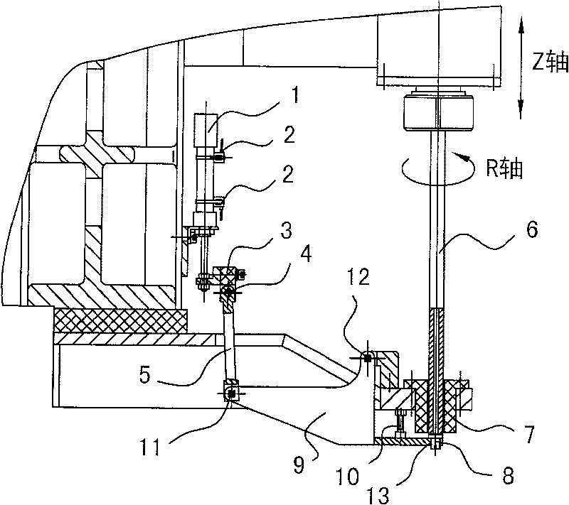
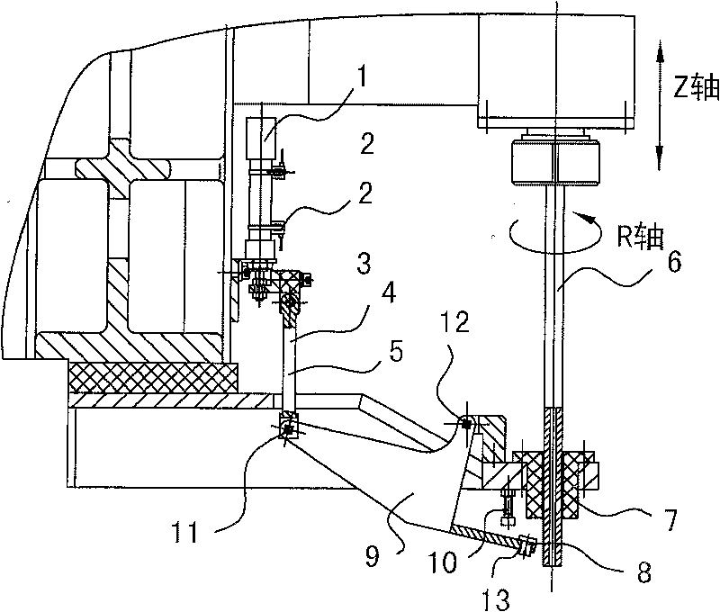
[0030] As attached figure 1 with figure 2 As shown, the online quick tool setting device is mainly composed of a cylinder 1, a connecting rod 5, a swing body 9, a swing positioning block 10, and a tool setting block 8. The cylinder 1 is used as a driving element, and the swing body 9 constitutes a swing mechanism. The driving element and the swing mechanism are both arranged on the base of the electric discharge milling machine tool in a fixed connection relationship with the electrode guide 7. The cylinder rod of the cylinder 1 is hinged with one end of the connecting rod 5 (see hinge point 4) through the connecting head 3 as the driving end, and the other end of the connecting rod 5 is hinged with the swing input end of the swing body 9 (see hinge point 11). The swing body 9 swings and supports (see the hinge point 12). A mounting seat 1...
Embodiment 2
[0034] Embodiment 2: An online fast tool setting device of a CNC high-efficiency electric discharge milling machine tool
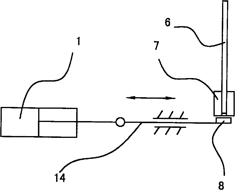
[0035] See image 3 As shown, in this embodiment, the motion mechanism adopts a sliding mechanism, and the driving element adopts a cylinder 1, an oil cylinder, a linear motor or an electromagnet with a reciprocating linear motion stroke. The sliding mechanism is mainly composed of a sliding body 14 arranged in a straight line slidingly. One end of the sliding body 14 is used as a motion input connection end to connect with the driving end of the driving element, and the other end of the sliding body 14 is used as a motion output connection end to install the tool counter block 8 . The sliding body 14 sends the tool setting reference surface of the tool setting block 8 into and out of the guide hole port of the electrode guide 7 in a sliding and telescopic manner.
[0036] In this embodiment, the driving element can also be changed to a rotating electric machi...
Embodiment 3
[0037] Embodiment 3: An online fast tool setting device of a numerically controlled high-efficiency electric discharge milling machine tool
[0038] See Figure 4 As shown, in this embodiment, the motion mechanism adopts a rotating mechanism, and the driving element adopts a rotating motor 16 that can rotate forward and backward. The rotating mechanism is mainly composed of a rotating body 15 rotatably arranged. One end of the rotating body 15 is used as a motion input connection end to be connected to the rotating motor 16 in transmission, and a certain point on the circumference of the rotating body 15 is used as a motion output connection end to install the tool counter block 8. , The rotating body 15 sends the tool setting reference surface of the tool setting block 8 into and out of the guide hole port of the electrode guide 7 in a rotating manner.
[0039] In this embodiment, the driving element can also be changed to a cylinder, oil cylinder, linear motor or electromagnet w...
PUM
 Abstract
Description
Claims
Application Information
 - R&D
- Intellectual Property
- Life Sciences
- Materials
- Tech Scout
- Unparalleled Data Quality
- Higher Quality Content
- 60% Fewer Hallucinations
Browse by: Latest US Patents, China's latest patents, Technical Efficacy Thesaurus, Application Domain, Technology Topic, Popular Technical Reports.
© 2025 PatSnap. All rights reserved.Legal|Privacy policy|Modern Slavery Act Transparency Statement|Sitemap|About US| Contact US: help@patsnap.com


