
Tilt-rotor plane operated and propelled by thrust scull and slipstream rudder

A technology of tilt rotor and slipstream rudder, which is applied in rotorcraft, aircraft parts, aircraft control, etc. It can solve the problem that the aeroelastic characteristics are difficult to meet the design requirements, the propulsion efficiency is not very high, and the lift and drag characteristics of forward flight are not very good, etc. question

Inactive Publication Date: 2009-05-06
BEIHANG UNIV
View PDF0 Cites 54 Cited by
  • Summary
  • Abstract
  • Description
  • Claims
  • Application Information

AI Technical Summary

Problems solved by technology

Since the rotor blades of this tiltrotor can only function as super-large-diameter propellers, the propulsion efficiency is not very high during forward flight, which also limits the aircraft to reach a greater forward speed.
In addition, due to the heavy rotor power nacelle hanging on the wing tip, the strength and stiffness of the wing limit the wingspan of this type of aircraft, so the forward flight lift and drag characteristics of this tilt rotor aircraft are not very good, and the aeroelasticity is also very poor. Difficult to meet design requirements

Method used


Image

  • Tilt-rotor plane operated and propelled by thrust scull and slipstream rudder
  • Tilt-rotor plane operated and propelled by thrust scull and slipstream rudder
  • Tilt-rotor plane operated and propelled by thrust scull and slipstream rudder

Examples


Embodiment Construction

[0043] See figure 1 , figure 2 , image 3 , Figure 4 , Figure 5 , Figure 6 , Figure 7 , Figure 8 , shown in Figure 9, its specific implementation is as follows:

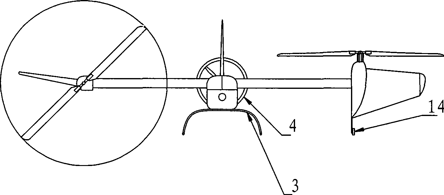
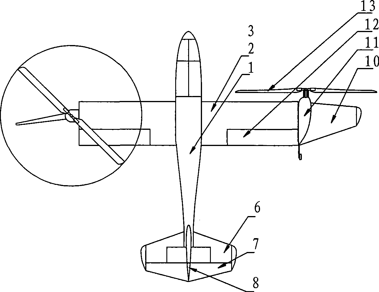
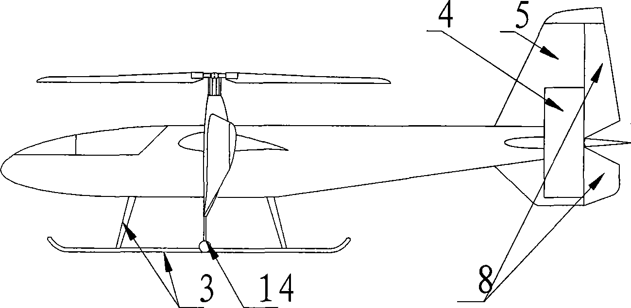
[0044] The invention is a tilt rotor aircraft controlled and propelled by a thrust tail rotor and a slipstream rudder, and adopts a design of parallel double rotors and a conventional aerodynamic layout. It is composed of fuselage 1, wing 2, empennage, thrust tail rotor and slipstream rudder system, landing gear, power and fuel system, transmission system, rotor system, rotor nacelle, and rotor nacelle tilting system. The wing 2 is installed on both sides of the middle section of the fuselage 1, the empennage is installed on the tail of the fuselage 1, the thrust tail rotor and the slipstream rudder system are installed on the empennage, the main body of the landing gear is located on the belly of the fuselage 1, and the power and fuel systems are installed on the fuselage 1. The inside of the middle se...


PUM


Abstract

A tilt rotor aircraft adopting a thrust tail rotor and a slipstream rudder for operation and propelling and a design of two parallel rotary wings and common pneumatic distribution comprises an airframe, wings, an empennage, a system of thrust tail rotor and slipstream rudder, an undercarriage, a power-fuel system, a transmission system, a rotary wing system, a rotary-wing nacelle and a tilt rotor system of the rotary-wing nacelle. The aircraft adopts the system of the thrust tail rotor and slipstream rudder to operate the VTOL and the pitching and drifting of the forward flight; the system comprising the thrust tail rotor, an elevator and a rudder is arranged on the empennage; a tilting wingtip appears as a small-area wing which is arranged on the outside of the rotary-wing nacelle and rotates together with the rotary-wing nacelle; the plane shape of the tilting wingtip appears as a trapezoid of leading edge sweepback and trailing edge sweepforward and the aspect ratio is 1.5 and the area of the tilting wingtip occupies about 15 to 20 percent of the whole wing area and the tilting wingtip is just integrated with the appearance of the rotary-wing nacelle and fixedly connected with a nacelle bevel gear box. The tilt rotor aircraft is a novel aircraft type with the development potential and prosperous prospect.

Description

(1) Technical field: [0001] The invention relates to a tilting rotor aircraft, in particular to a tilting rotor aircraft which adopts a thrust tail rotor and a slipstream rudder for manipulation and propulsion. The invention belongs to the technical field of vertical take-off and landing aircraft and aviation vehicle design. (two) background technology: [0002] In order to design an aircraft that has both the vertical take-off and landing performance of a helicopter and the high-speed, long-range performance of a fixed-wing aircraft, humans have proposed various vertical take-off and landing aircraft, including compound helicopters, equipped with thrust vectoring engines or Lift powered jet aircraft, rotary wing aircraft, tilt ducted propeller aircraft, tilt rotor aircraft, etc. For specific information, please refer to the paper published by American scholar Rob Ransone: An Overview of VSTOLAircraft and Their Contributions (An Overview of VSTOLAircraft and Their Contribut...

Claims


Application Information

Patent Timeline
IPC IPC(8): B64C27/02B64C27/28B64C17/00B64C27/08
Inventor 吴大卫胡继忠曾洪江
Owner BEIHANG UNIV
Learn More