Method for cooling steel pipe

A cooling method and steel pipe technology, applied in furnaces, heat treatment equipment, quenching devices, etc., to achieve excellent performance, low cost, and uniform cooling

Inactive Publication Date: 2012-07-04
攀钢集团成都钢铁有限责任公司
View PDF0 Cites 0 Cited by
  • Summary
  • Abstract
  • Description
  • Claims
  • Application Information

AI Technical Summary

Problems solved by technology

At present, there are no relevant reports on special cooling methods for medium and thick-walled steel pipes

Method used


Image

  • Method for cooling steel pipe
  • Method for cooling steel pipe
  • Method for cooling steel pipe

Examples


Embodiment Construction

[0022] The specific implementation of the present invention will be further described below in conjunction with the examples and drawings, and the present invention is not limited to the scope of the examples.

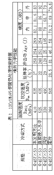
[0023] EXAMPLE 12Cr1MoVG steel pipe with a specification of φ457×50 was subjected to normalizing heat treatment.

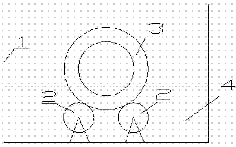
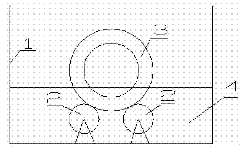
[0024] Before the heat treatment, the water in the cooling tank 1 is emptied (see the structural diagram of the equipment used) figure 1 ). After the steel pipe 3 is normalized and heated out of the furnace, the steel pipe 3 is hoisted into the cooling tank 1 and placed on the roller 2. The roller 2 is driven by the motor to rotate, and the rotating roller 2 drives the steel pipe to rotate, and water is injected into the cooling tank 1. The water surface rises, and when the water touches the outer surface of the steel pipe 3, the steel pipe 3 starts to cool from the outer surface; The inner and outer surfaces can be cooled evenly at the same time.


PUM


Abstract

The invention relates to a steel pipe cooling method, which belongs to the field of steel pipe heat treatment. The technical problem solved by the invention is to provide the steel pipe cooling method which can satisfy the demand for cooling medium and thick-wall steel pipes. The steel pipe cooling method comprises the following steps of placing a steel pipe to be parallel to the liquid level of a liquid cooling medium, dipping part of the steel pipe in the liquid cooling medium, rotating the steel pipe and cooling the steel pipe. The method has the advantages of simple process, simple equipment, low cost and broad application prospects.

Description

technical field [0001] The invention relates to a cooling method for steel pipes and belongs to the field of steel pipe heat treatment. Background technique [0002] Steel pipe heat treatment refers to the process of making steel pipes achieve certain properties through certain heating and cooling processes. The heat treatment process of steel pipe mainly includes normalizing, normalizing plus tempering, quenching and tempering, etc. The cooling method of steel pipe normalizing is cooling in still air, referred to as air cooling. Quenching and tempering of steel pipes refers to quenching and tempering. Quenching cooling methods include air cooling, fog cooling, immersion in liquid cooling medium, etc. In addition to heat treatment, hot-rolled seamless steel pipes also use different cooling methods after rolling to make the properties of the steel pipes meet the design requirements. [0003] For the cooling method of such slender rods as steel pipes immersed in liquid cool...

Claims


Application Information

Patent Timeline
Patent Type & Authority Patents(China)
IPC IPC(8): C21D9/08C21D1/63
Inventor 江健郭元蓉
Owner 攀钢集团成都钢铁有限责任公司
Why Eureka
Try Eureka