Supercharge Your Innovation With Domain-Expert AI Agents!

Light guide board, back light source and LCD

A technology of liquid crystal display and light guide plate, applied in static indicators, light guides, optics, etc., can solve problems such as inability to realize light control, and achieve excellent color resolution, effective and color resolution effects

Inactive Publication Date: 2009-05-06
BEIJING BOE OPTOELECTRONCIS TECH CO LTD
View PDF0 Cites 19 Cited by
  • Summary
  • Abstract
  • Description
  • Claims
  • Application Information

AI Technical Summary

Problems solved by technology

[0006] The purpose of the present invention is to provide a light guide plate structure to realize the binary modulation of the incident light on the panel, aiming at the defect that the existing technology can only simply reflect the incident light and cannot realize the control of the light.

Method used


Image

  • Light guide board, back light source and LCD
  • Light guide board, back light source and LCD
  • Light guide board, back light source and LCD

Examples


Embodiment Construction

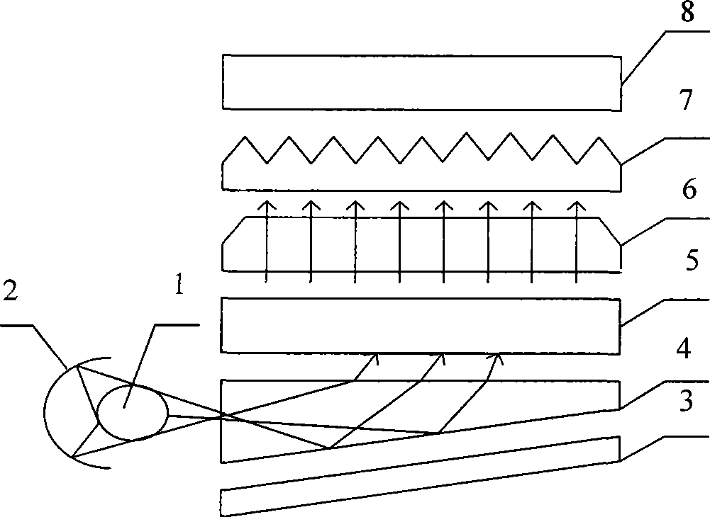
[0020] The present invention will be described in further detail below in conjunction with the accompanying drawings.

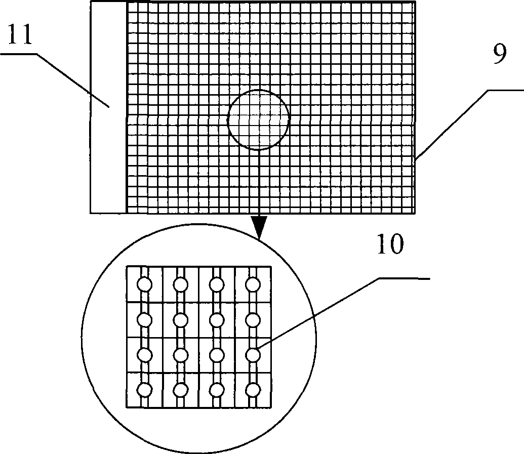
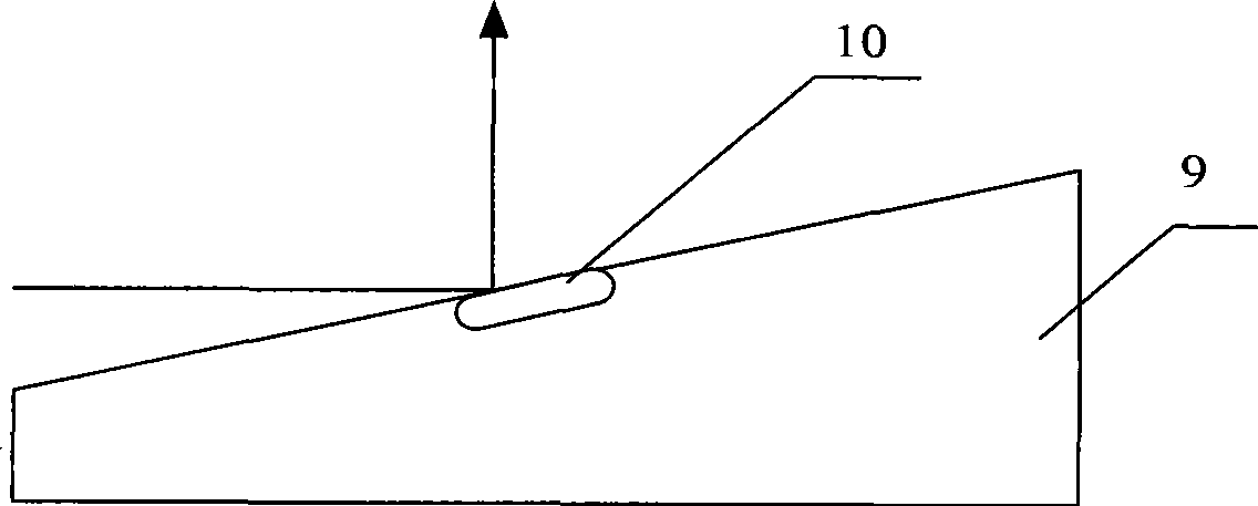
[0021] The invention provides a light guide plate structure, such as figure 2 As shown, the light guide plate of the present invention comprises a light guide plate body 9 with a micro-mirror, a series of micro-mirrors 10 formed on the light guide body 9 with a micro-mirror, and the size of each mirror is all between 1 micron and 1 micron. On the order of about millimeters, preferably about 10 microns. And its shape can be designed into various shapes such as rectangle, circle or rhombus, wherein the micro-mirrors 10 form an array structure, and the micro-mirrors 10 are controllable micro-mirrors, which are controlled by the control circuit 11 . In the initial state, that is, when the control circuit 11 does not apply voltage to the micromirrors, all the micromirrors 10 remain image 3 In the case of (only one micro-mirror 10 is used as an example in the f...


PUM

PropertyMeasurementUnit
Sizeaaaaaaaaaa

Abstract

The invention discloses a structure of a light guide plate, which is composed of a light guide plate body, wherein a series of micro light reflectors are formed on the light guide plate body; the micro light reflectors are controllable micro light reflectors and can deflect around the light guide plate body. The invention also discloses a backlight source adopting the light guide plate, and a liquid crystal display adopting the backlight source. One or a plurality of micro light reflectors are arranged in each pixel overlay region of the liquid crystal display. By the series of micro light reflectors formed on the light guide plate body and controlling the micro light reflectors, the controllability of the emergent light of the backlight source is realized; by matching the display control of the liquid crystal display, the dualization control of a TFT-LCD backlight system is realized.

Description

technical field [0001] The invention relates to a thin film transistor liquid crystal display (hereinafter referred to as TFT-LCD), in particular to a light guide plate of a thin film transistor liquid crystal display, a backlight source and a liquid crystal display using the light guide plate. Background technique [0002] TFT-LCD occupies a dominant position in the current flat panel display market because of its small size, low power consumption, and no radiation. TFT-LCD devices are formed by combining array glass substrates and color filter glass substrates. On the array substrate, gate lines and signal lines defining pixel areas are arranged to cross each other, and pixel electrodes and thin film transistors are arranged in each pixel area. Driving signals are applied to the gate lines, and image data is applied to the pixel electrodes through the signal lines. A black matrix is ​​arranged on the color filter substrate to prevent light from passing through areas othe...

Claims


Application Information

Patent Timeline
IPC IPC(8): G02B6/00G02B5/08G02B1/02G02B26/08G02F1/13357G02F1/133G02F1/1335
CPCG02B6/0055
Inventor 郭建金基用周伟峰明星
Owner BEIJING BOE OPTOELECTRONCIS TECH CO LTD
Features
  • R&D
  • Intellectual Property
  • Life Sciences
  • Materials
  • Tech Scout
  • Unparalleled Data Quality
  • Higher Quality Content
  • 60% Fewer Hallucinations
Learn More